Wiring configuration, Rtd and thermistor connections – Measurement Computing USB-5203 User Manual
Page 12
USB-5203 User's Guide
Sensor Connections
12
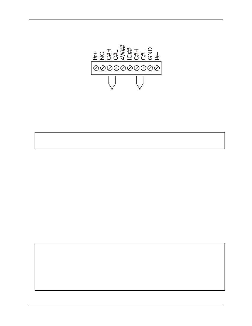
Wiring configuration
Connect the thermocouple to the USB-5203 using a differential configuration, as shown in Figure 3.
Figure 3. Typical thermocouple connection
The USB-5203
GND
pins are isolated from earth ground, so connecting thermocouple sensors to voltages
referenced to earth ground is permissible as long as the isolation between the GND pins (9, 19, 28, 38) and earth
ground is maintained.
When thermocouples are attached to conductive surfaces, the voltage differential between multiple
thermocouples must remain within ±1.4 V. For best results, we recommend the use of insulated or ungrounded
thermocouples when possible.
Maximum input voltage between analog input and ground
The absolute maximum input voltage between an analog input and the isolated GND pins is ±25 VDC when the
USB-5203 is powered on, and ±40 VDC when the USB-5203 is powered off.
If you need to increase the length of your thermocouple, use the same type of thermocouple wires to minimize
the error introduced by thermal EMFs.
RTD and thermistor connections
A resistance temperature detector (RTD) measures temperature by correlating the resistance of the RTD
element with temperature. A thermistor is a thermally-sensitive resistor that is similar to an RTD in that its
resistance changes with temperature – thermistors show a large change in resistance that is proportional to a
small change in temperature. The main difference between RTD and thermistor measurements is the method
used to linearize the sensor data.
RTDs and thermistors are resistive devices that require an excitation current to produce a voltage drop that can
be measured differentially across the sensor. The device has four built-in current excitation sources (±I1 to ±I4)
for measuring resistive type sensors. Each current excitation terminal is dedicated to one channel pair.
The USB-5203 makes two, three, and four-wire measurements of RTDs (100
Ω platinum type) and thermistors.
Use InstaCal to select the sensor type and the wiring configuration. Once the resistance value is calculated, the
value is linearized in order to convert it to a temperature value. A 32-bit floating point value in either
temperature or resistance is returned by software.
RTD maximum resistance
Resistance values
greater than 660 Ω cannot be measured in RTD mode. The 660 Ω resistance limit includes the
total resistance across the current excitation (±Ix) pins, which is the sum of the RTD resistance and the lead
resistances.
Thermistor maximum resistance
Resistance values
greater than 180 kΩ cannot be measured in thermistor mode. The 180 kΩ resistance limit
includes the total resistance across the current excitation (±Ix) pins, which is the sum of the thermistor
resistance and the lead resistance.