Compatible sensors, Accuracy, Thermocouple measurement accuracy – Measurement Computing USB-5203 User Manual
Page 23
USB-5203 User's Guide
Specifications
23
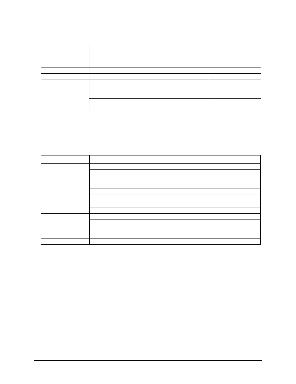
Table 2. Channel configuration specifications
Sensor Category
Conditions
Max number of
sensors (all channels
configured alike)
Disabled (Note 1)
Thermocouple
J, K, S, R, B, E, T, or N
8 differential channels
Semiconductor sensor
8 differential channels
RTD and thermistor
2-wire input configuration with a single sensor per channel pair
4 differential channels
2-wire input configuration with two sensors per channel pair
8 differential channels
3-wire configuration with a single sensor per channel pair
4 differential channels
4-wire input configuration with a single sensor per channel pair
4 differential channels
4-wire input configuration with two sensors per channel pair
8 differential channels
Note 1:
The factory default configuration is Disabled. In Disabled mode, analog inputs are disconnected from
the terminal blocks and all of the A/D inputs are internally grounded. This mode also disables each of
the current excitation sources.
Compatible sensors
Table 3. Compatible sensor type specifications
Parameter
Specification (°C)
Thermocouple
J: –210 to 1200
K: –270 to 1372
R: –50 to 1768
S: –50 to 1768
T: –270 to 400
N: –270 to 1300
E: –270 to 1000
B: 0 to 1820
RTD
100
Ω PT (DIN 43760: 0.00385 ohms/ohm/°C)
100
Ω PT (SAMA: 0.003911 ohms/ohm/°C)
100
Ω PT (ITS-90/IEC751:0.0038505 ohms/ohm/°C)
Thermistor
Standard 2,252
Ω through 30,000 Ω
Semiconductor / IC
LM35, TMP35 or equivalent
Accuracy
Thermocouple measurement accuracy
Thermocouple measurement accuracy specifications include linearization, cold-junction compensation and
system noise. These specs are for one year, or 3000 operating hours, whichever comes first, and for operation of
the device between 15 °C and 35 °C. For measurements outside this range, add ±0.5° to the maximum error
shown. There are CJC sensors on each side of the module. The accuracy listed above assumes the screw
terminals are at the same temperature as the CJC sensor. Errors shown do not include inherent thermocouple
error. Please contact your thermocouple supplier for details on the actual thermocouple error.
Thermocouples must be connected to the device such that they are floating with respect to GND (pins 9, 19, 28,
38). The device GND pins are isolated from earth ground, so connecting thermocouple sensors to voltages
referenced to earth ground is permissible as long as the isolation between the GND pins and earth ground is
maintained.
When thermocouples are attached to conductive surfaces, the voltage differential between multiple
thermocouples must remain within ±1.4 V. For best results, MCC recommends using insulated or ungrounded
thermocouples when possible.