Digital input/output – Measurement Computing USB-5203 User Manual
Page 26
USB-5203 User's Guide
Specifications
26
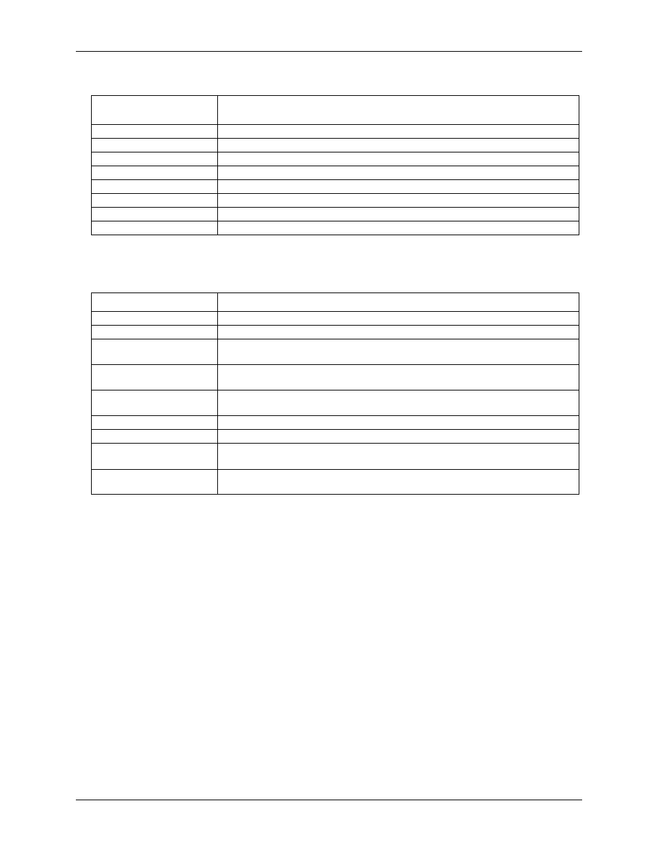
Table 9. Throughput rate specifications
Number of Input
Channels
Maximum Throughput
1
2 Samples/second
2
2 S/s on each channel, 4 S/s total
3
2 S/s on each channel, 6 S/s total
4
2 S/s on each channel, 8 S/s total
5
2 S/s on each channel, 10 S/s total
6
2 S/s on each channel, 12 S/s total
7
2 S/s on each channel, 14 S/s total
8
2 S/s on each channel, 16 S/s total
Digital input/output
Table 10. Digital input/output specifications
Parameter
Specification
Digital type
CMOS
Number of I/O
8 (DIO0 through DIO7)
Configuration
Independently configured for input or output.
Power on reset is input mode unless bit is configured for alarm.
Pull up/pull-down
configuration
All pins pulled up to +5 V via 47 K resistors (default). Pull down to ground (GND) also
available.
Digital I/O transfer rate
(software paced)
Digital input – 50 port reads or single bit reads per second typ
Digital output – 100 port writes or single bit writes per second typ
Input high voltage
2.0 V min, 5.5 V absolute max
Input low voltage
0.8 V max, –0.5 V absolute min
Output low voltage
(IOL = 2.5 mA)
0.7 V max
Output high voltage
(IOH = –2.5 mA)
3.8 V min
Note 2:
All ground pins on the device (pins 9, 19, 28, 38) are common and are isolated from earth ground. If a
connection is made to earth ground when using digital I/O and conductive thermocouples, the
thermocouples are no longer isolated. In this case, thermocouples must not be connected to any
conductive surfaces that may be referenced to earth ground.