Analog output calibration – Measurement Computing USB-3110 User Manual
Page 19
USB-3110 User's Guide
Specifications
19
Note 3:
The maximum differential non-linearity specification applies to the entire 0 to 50 °C temperature
range of the USB-3110. This specification also accounts for the maximum errors due to the
software calibration algorithm (in Calibrated mode only) and the DAC8554 digital to analog
converter non-linearities.
Note 4:
The USB-3110 voltage outputs should not be kept in a short-circuit condition for longer than the
specified limit of 100 ms. For those applications that may potentially exceed the 40 mA
maximum current limit or the 100 ms short-circuit condition, external current limiting must be
used to prevent potential damage to the USB-3110.
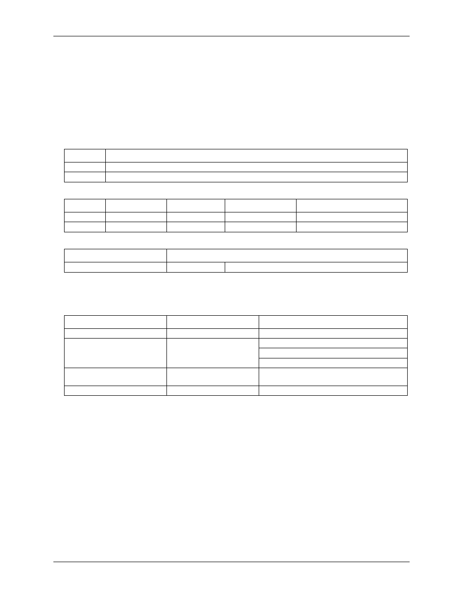
Table 2. Absolute accuracy specifications
– calibrated output, VOUTx Rload = 20 mA fixed resistive load
Range
Accuracy (±LSB)
±10 V
14.0
0 to 10 V
22.0
Table 3. Absolute accuracy components specifications
– calibrated output
Range
% of reading
Offset (±mV)
Temp drift (%/°C)
Absolute accuracy at FS (±mV)
±10 V
±0.0183
1.831
0.00055
3.661
0 to 10 V
±0.0183
0.915
0.00055
2.746
Table 4. Relative accuracy specifications
Range
Relative accuracy (±LSB)
±10 V , 0 to 10 V
4.0 typ.
12.0 max.
Analog output calibration
Table 5. Analog output calibration specifications
Parameter
Conditions
Specifications
Recommended warm-up time
15 minutes min.
On-board precision reference
DC level: 5.000 V ±1 mV max.
Tempco: ±10 ppm/°C max.
Long term stability: ±10 ppm/SQRT(1000 hrs)
Calibration method
Voutx Rload = 20 mA fixed
resistive load
Software calibration
Calibration interval
1 year