Power led, Screw terminal banks, Screw terminal – pins 1-28 – Measurement Computing USB-3110 User Manual
Page 13: Screw terminal – pins 29-56
USB-3110 User's Guide
Functional Details
13
Power LED
The power LED lights up when the USB-3110 is receiving power from the AC power adapter.
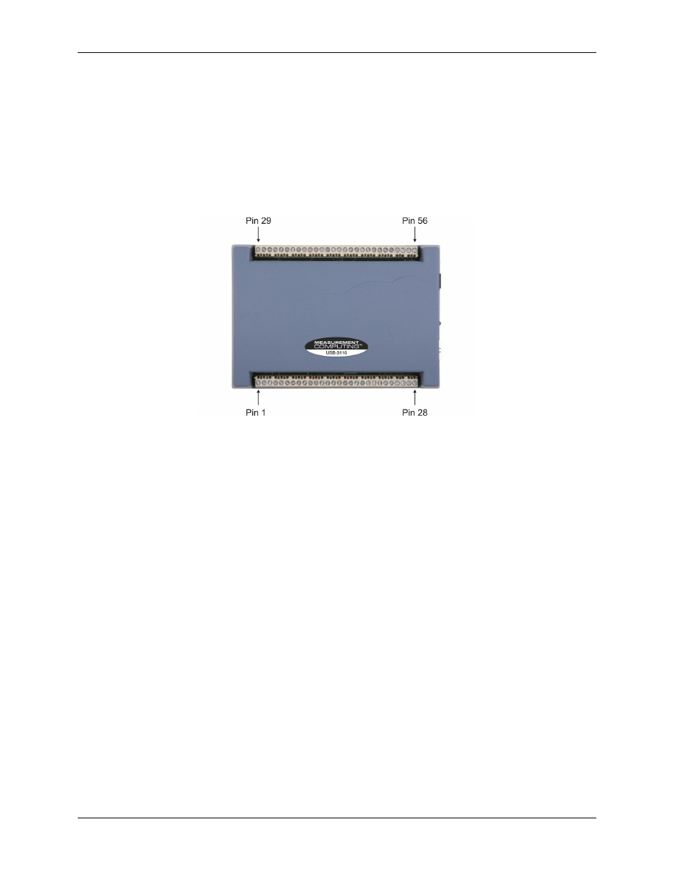
Screw terminal banks
The USB-3110 has two rows of screw terminals—one row on the top edge of the housing, and one row on the
bottom edge. Each row has 28 connections. Use 16 AWG to 30 AWG wire gauge when making screw terminal
connections. Pin numbers are identified in Figure 4.
Figure 4. USB-3110 screw terminal pin numbering
Screw terminal
– pins 1-28
The screw terminals on the bottom edge of the USB-3110 (pins 1 to 28) provide the following connections:
Two analog voltage output connections (
VOUT0, VOUT2
)
Four analog ground connections (
AGND
)
Eight digital I/O connections (
DIO0
to
DIO7
)
Screw terminal
– pins 29-56
The screw terminals on the top edge of the USB-3110 (pins 29 to 56) provide the following connections:
Two analog voltage output connections (
VOUT1, VOUT3
)
Four analog ground connections (
AGND
)
One SYNC terminal for external clocking and multi-unit synchronization (
SYNCLD
)
Three digital ground connections (
DGND
)
One external event counter connection (
CTR
)
One digital I/O pull-down resistor connection (
DIO CTL
)
One voltage output power connection (
+5 V
)