Specifications, Analog voltage output, Chapter 4 – Measurement Computing USB-3110 User Manual
Page 18
18
Chapter 4
Specifications
Typical for 25 °C unless otherwise specified.
Specifications in italic text are guaranteed by design.
Analog voltage output
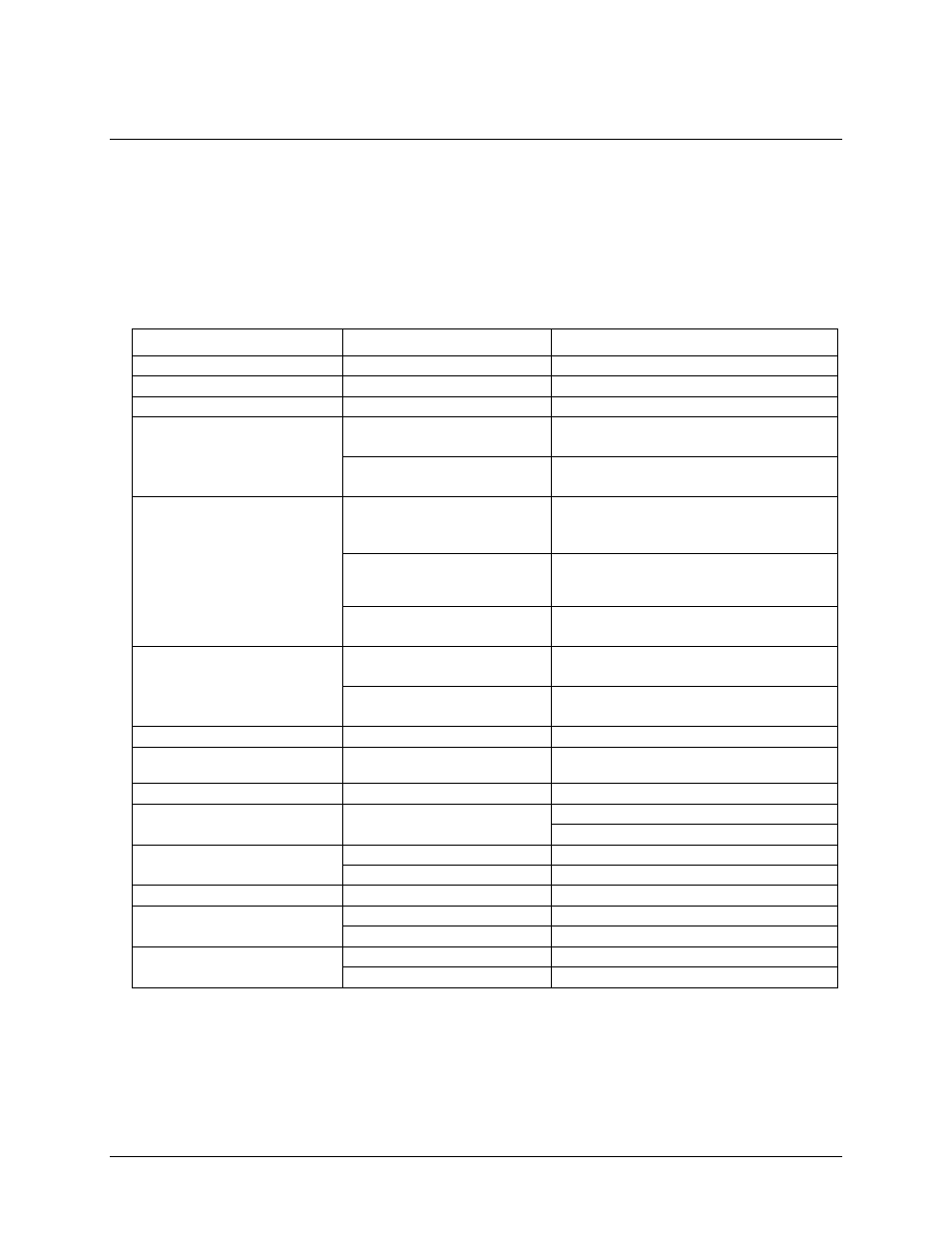
Table 1. Analog voltage output specifications
Parameter
Conditions
Specifications
Digital to Analog converter
DAC8554
Number of channels
4
Resolution
16 bits
Output ranges
Calibrated
±10 V, 0 to 10 V
Software configurable
Un-calibrated
±10.2 V, -0.04 to 10.08 V
Software configurable
Output Transient
±10 V to (0 to 10 V) or
(0 to 10 V) to ±10 V range
selection (Note 1)
Duration 5 µS typ.
Amplitude 5 V p-p typ.
Host PC is reset, powered up,
suspended or a reset command is
issued to device. (Note 2)
Duration 2 S typ.
Amplitude 2 V p-p typ.
Initial power on.
Duration 50 mS typ.
Amplitude 5 V peak typ
Differential non-linearity
(Note 3)
Calibrated
±1.25 LSB typ.
-2 LSB to +1 LSB max.
Un-calibrated
±0.25 LSB typ.
±1 LSB max.
Current output (Note 4)
VOUTx pins
±40 mA max.
Output short-circuit protection
(Note 4)
VOUTx connected to AGND
100 mS max.
Output coupling
DC
Power on and reset state
DACs clear to zero-scale: 0 V, ±50 mV typ.
Output Range: 0-10V
Output noise
0 to 10 V range
14.95 µVrms typ.
±10 V range
31.67 µVrms typ.
Settling time
to 1 LSB accuracy
25 µS typ.
Slew rate
0 to10 V range
2.0 V/µS typ.
±10 V range
4.0 V/µS typ.
Throughput
single channel
100 Hz max., system dependent
multi-channel
100 Hz/#ch max., system dependent
Note 1:
The USB-3110 output voltage level defaults to 0V whenever the output voltage range is
reconfigured.
The USB-3110 output voltage level will also default to 0V:
1. Whenever the host PC is reset, shut down or suspended
2. If a reset command is issued to the device.
Note 2:
The duration of this particular output transient is highly dependent on the enumeration process of
the host PC. Typically the output of the USB-3110 is stable after 2 seconds.