Analog outputs (ao 0 to ao 3), Usb connector, Strain relief slot for usb cable – Measurement Computing USB-3101FS User Manual
Page 12: High-voltage applications, Connecting a load
USB-3101FS User's Guide
Functional Details
12
Analog outputs (AO 0 to AO 3)
The voltage output range for each channel is set at ±10 V. The channel outputs may be updated individually or
simultaneously.
USB connector
The USB connector provides +5 V power and communication. The voltage supplied through the USB connector
is system-dependent, and may be less than 5 V. No external power supply is required.
LED
The LED indicates the device status. It uses up to 5 mA of current and cannot be disabled. Refer to the
following table for the possible LED states.
LED States
LED State
Device status
Not lit
The device is not connected to a USB port or hub.
Continuous single-blink
The device is operating normally.
Continuous double-blink
The device is connected to a USB 1.1 Full-Speed port or hub, which may affect
performance.
Optimum performance requires connections to a USB 2.0 Hi-Speed host controller
(480 Mbps) and USB 2.0 high-speed hubs.
Strain relief slot for USB cable
Use the strain relief slot to keep the USB cable from disconnecting from the device inadvertently. Feed a tie
wrap through the slot and secure to the USB cable when it is connected to the device.
High-voltage applications
For high voltage applications, we recommend using the ACC-107 backshell with ten-position connector block
to ensure that the terminals are not accessible. The backshell also provides strain relief to protect the screw
terminals.
Figure 4. ACC-107 backshell with ten-position connector block
Additional details on this product are available on our web site at
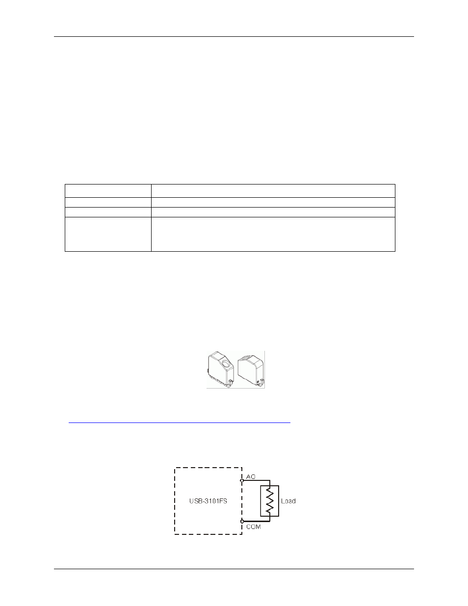
Connecting a load
Connect the positive lead of the load to the AO terminal, and the ground of the load to the COM terminal.
Figure 5. Connecting a load to the device