Functional details, Components, Thermocouple input – Measurement Computing USB-2001-TC User Manual
Page 9: Thermocouple with bare wire leads
9
Chapter 3
Functional Details
Components
The USB-2001-TC has the following components:
Thermocouple input
USB cable and connector
LED indicator
Thermocouple input
You can connect one thermocouple to a standard thermocouple subminiature connector. Thermocouple types J,
K, R, S, T, N, E, and B are supported. The thermocouple type you select will depend on your application needs.
Review the temperature ranges and accuracies of each type to determine which thermocouple is best suited for
the application.
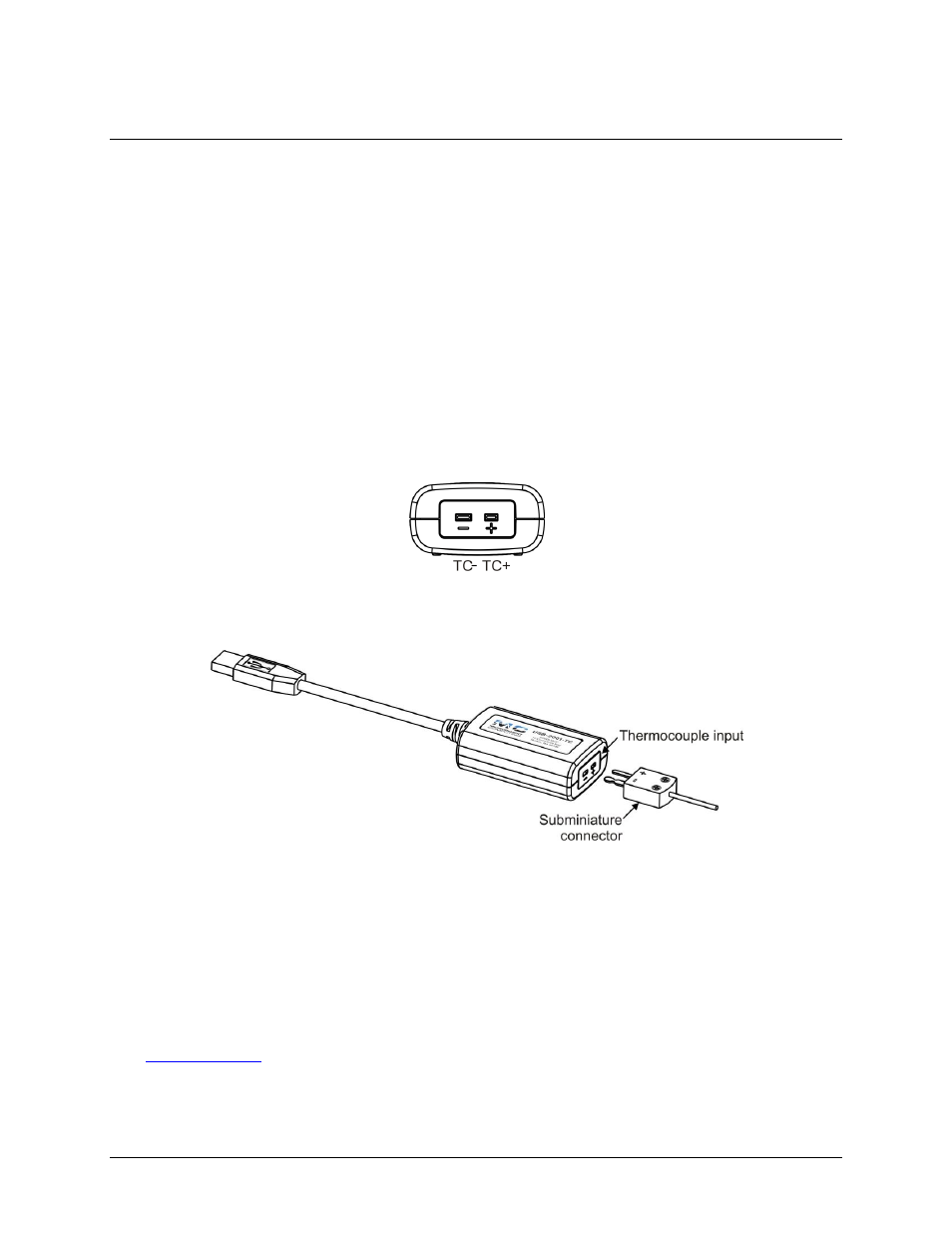
Connect the positive lead of the thermocouple to the TC+ terminal, and the negative lead of the thermocouple to
the TC– terminal.
Figure 3. TC input terminals
If you are unsure which of the thermocouple leads is positive and which is negative, check the thermocouple
documentation or the thermocouple wire spool.
Figure 4. Connecting a thermocouple
For best results, use insulated or ungrounded thermocouples when possible. If you need to increase the length of
your thermocouple, use the same type of thermocouple wires to minimize the error introduced by thermal
EMFs.
Temperature measurement errors depend in part on the thermocouple type, the temperature being measured, the
accuracy of the thermocouple, and the cold-junction temperature.
Thermocouple with bare wire leads
If your thermocouple has bare wire leads, you can purchase a screw terminal subminiature connector to use with
the USB-2001-TC. These are available from a number of suppliers, such as Nanmac Corporation
. For the best accuracy, the subminiature connector type and thermocouple type should
match.