Usb connector, Led indicator, Analog input circuitry – Measurement Computing USB-2001-TC User Manual
Page 10: Open-thermocouple detection (otd)
USB-2001-TC User's Guide
Functional Details
10
Figure 5 shows the screw terminal connector wiring.
Figure 5. Screw terminal connector wiring
USB connector
The USB connector provides +5 V power and communication. The voltage supplied through the USB connector
is system-dependent, and may be less than 5 V. No external power supply is required.
LED indicator
The device LED indicates the communication status, and uses up to 5 mA of current.
LED behavior
Condition
Specification
On – steady green
The device is powered and ready for operation.
On – blinking green
The device is powered, but not yet enumerated by the USB.
Off
The device is not powered or is in USB suspend.
Analog input circuitry
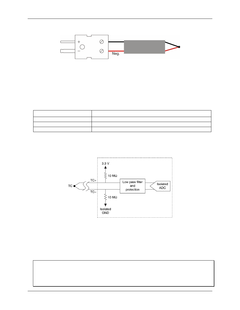
Figure 6 shows the analog input circuitry. The thermocouple channel passes through a differential filter and is
sampled by a 20-bit analog-to-digital converter (ADC).
Figure 6. Analog input circuitry
Open-thermocouple detection (OTD)
The USB-2001-TC is equipped with open-thermocouple detection. With OTD, any open-circuit condition at the
thermocouple sensor is detected by the software. An open channel is detected by driving the input voltage to a
positive value outside the range of the thermocouple output. The software recognizes this as an invalid reading
and returns the value "OTD". During an open thermocouple condition, some invalid values may be returned
before the open thermocouple is reported.
Check the STATUS value before reading temperature values
To ensure that valid temperature readings are returned, verify that the value of
STATUS
is
READY
before
taking measurements. Invalid temperature readings may be returned if the
STATUS
value is
BUSY
or
ERROR
.
A value of
BUSY
indicates that no new data is available. In this condition the same temperature value as
previously read is returned until the
STATUS
value changes to
READY
.