External clock input/output, Counter, Memory – Measurement Computing USB-1608HS User Manual
Page 26
USB-1608HS User's Guide
Specifications
26
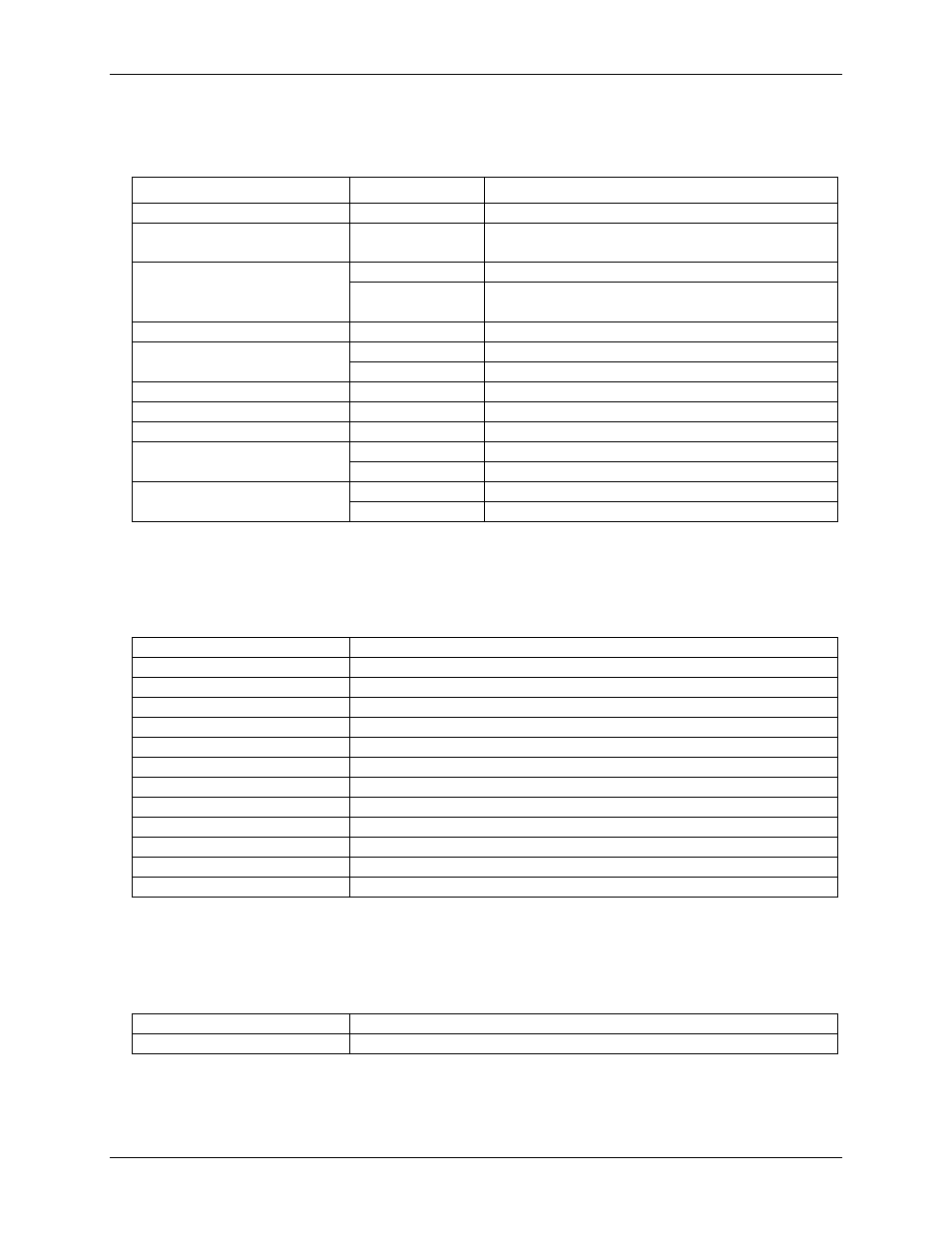
External clock input/output
Table 8. External clock I/O specifications
Parameter
Conditions
Specification
Pin names
SYNC_IN, SYNC_OUT
Pin type
SYNC_IN: Input
SYNC_OUT: Output
Pin descriptions
SYNC_OUT
Outputs A/D pacer clock.
SYNC_IN
Receives A/D pacer clock from external source.
Rising edge sensitive.
Input clock rate
250 kHz maximum.
Clock pulse width
SYNC_IN
1 µs minimum
SYNC_OUT
2 µs minimum
Input leakage current
±2.0 µA
Input high voltage
3.5 V minimum, 6.5 V absolute maximum
Input low voltage
1.5 V maximum, –0.5 V absolute minimum
Output high voltage (see Note 3)
IOH = –2.5 mA
3.3 V minimum
No load
3.8 V minimum
Output low voltage (see Note 3)
IOL = 2.5 mA
1.1 V maximum
No load
0.6 V maximum
Note 3:
SYNC_OUT is over-current protected with a 200 Ω series resistor.
Counter
Table 9. Counter specifications
Pin name (see Note 4)
CTR
Counter type
Event counter
Number of channels
1
Input type
TTL, rising edge triggered
Input source
CTR screw terminal
Resolution
32 bits
Schmidt trigger hysteresis
0.58 V to 0.93 V
Input leakage current
±5 µA
Maximum input frequency
1 MHz
High pulse width
500 ns minimum
Low pulse width
500 ns minimum
Input high voltage
2.4 V minimum, 6.5 V absolute maximum
Input low voltage
2.19 V maximum, –0.5 V absolute minimum
Note 4:
CTR is a Schmitt trigger input protected with a 1 kΩ series resistor.
Memory
Table 10. Memory specifications
Data FIFO
65536 samples, 131,072 bytes
EEPROM
512 bytes