Sync terminals (sync_in and sync_out), Trigger terminal (trig_in) – Measurement Computing USB-1608HS User Manual
Page 19
USB-1608HS User's Guide
Functional Details
19
SYNC terminals (SYNC_IN and SYNC_OUT)
You can use the
SYNC_IN
connection to externally pace the A/D conversions. The
SYNC_IN
terminal supports
TTL-level input signals of up to 250 kHz.
Use the
SYNC_OUT
connection to output the clock used for A/D conversions.
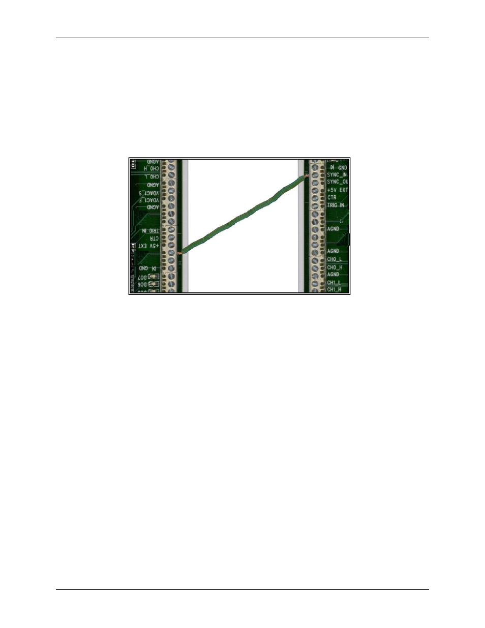
One example of the use of these two pins would be to synchronize with a second USB-1608HS and acquire
synchronized data from 16 channels. You can connect the
SYNC_OUT
pin of one USB-1608HS to the
SYNC_IN
pin of another USB-1608HS to acquire data synchronously from 16 channels.
Figure 10. Configuring for synchronous data acquisition
Trigger terminal (TRIG_IN)
The
TRIG_IN
connection is an external analog/digital trigger input.
With the analog trigger function, you can start and control acquisitions with an analog signal. The analog trigger
threshold is from -10 V to +10 V on the TRIG_IN pin. A 12-bit DAC sets the level for the threshold. The
threshold resolution in this mode is 4.88 mV.
The USB-1608HS has three trigger options that you must set.
Trigger above or trigger below
Level-sensitive or edge-sensitive
Retrigger on or retrigger off
Each trigger operation mode is explained next. In each case, a ±2 V triangle waveform is used as the
TRIG_IN
input source. The high threshold is set to 1.0 V, and the low threshold signal is set to -1.0 V.
In the following analog trigger signal diagrams, the bold portion of the waveform indicates the data acquired for
the given analog trigger mode.
SYNC_IN pin
SYNC_OUT pin