Power connector, Analog input terminals (ch0_l - ch7_h), Input configuration – Measurement Computing USB-1608HS User Manual
Page 15
USB-1608HS User's Guide
Functional Details
15
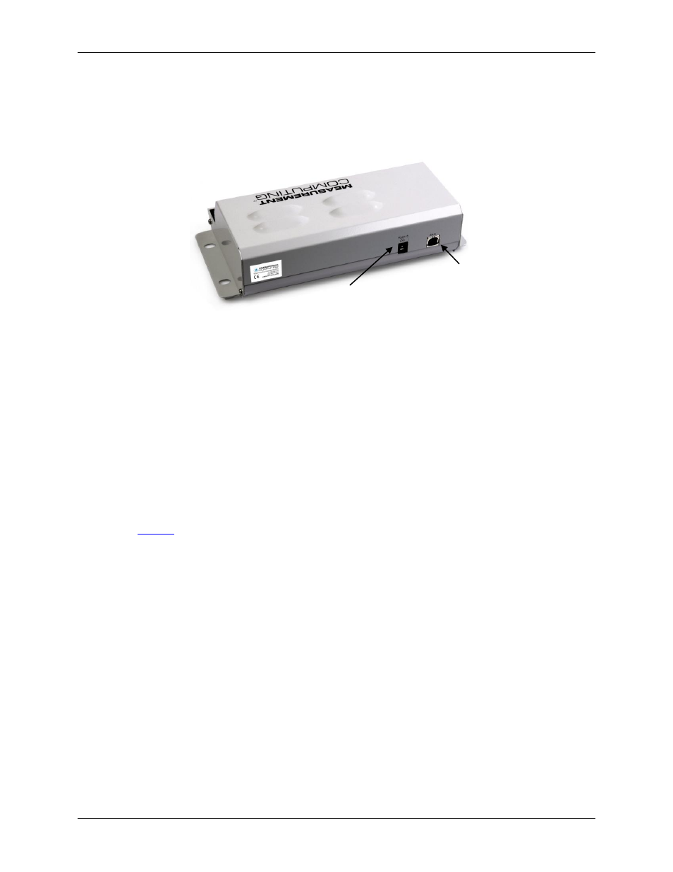
Power connector
Connect the external power adapter (MCC part number PS-5V2AEPS) to the power connector on the rear of the
USB-1608HS.
Figure 5. USB-1608HS external components
– rear view
Analog input terminals (CH0_L - CH7_H)
You can connect up to eight analog input connections to these screw terminal pins:
CH0_H and CH0_L
CH1_H and CH1_L
CH2_H and CH2_L
CH3_H and CH3_L
CH4_L and CH4_H
CH5_L and CH5_H
CH6_L and CH6_H
CH7_L and CH7_H
Refer to
on page 14 for the location of these pins.
Input configuration
Analog signals are referenced to analog ground (AGND). Single-ended mode requires two wires:
The wire carrying the signal to be measured connects to CHx_H.
The second wire connects to AGND.
Differential mode requires three wires:
The wire carrying the positive portion of the differential signal to be measured connects to CHx_H.
The wire carrying the negative portion of the differential signal to be measured connects to CHx_L.
The analog ground reference wire connects to AGND.
The input voltage ranges are ±10 V, ±5 V, ±2.0 V, ±1.0 V. The following image illustrates a typical
single-ended measurement connection.
USB connector
Power connector