Differential mode pinout – Measurement Computing USB-1608GX-2AO-OEM User Manual
Page 24
USB-1608GX-2AO-OEM User's Guide
Specifications
24
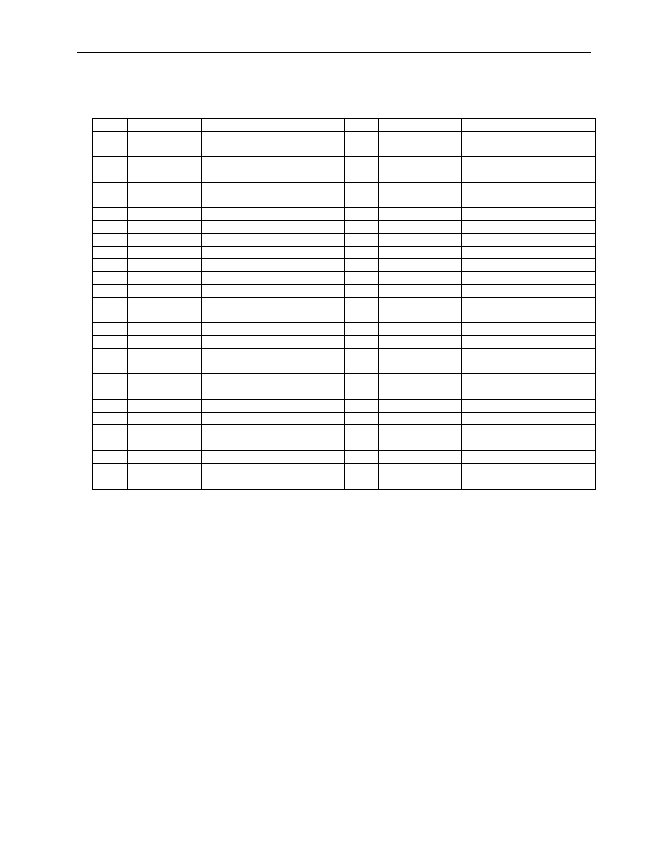
Differential mode pinout
Table 21. 8-channel differential mode pinout
Pin
Signal Name
Description
Pin
Signal Name
Description
1
CH0H
Channel 0 HI
29
CH7L
Channel 7 LO
2
CH0L
Channel 0 LO
30
CH7H
Channel 7 HI
3
AGND
Analog ground
31
AGND
Analog ground
4
CH1H
Channel 1 HI
32
CH6L
Channel 6 LO
5
CH1L
Channel 1 LO
33
CH6H
Channel 6 HI
6
AGND
Analog ground
34
AGND
Analog ground
7
CH2H
Channel 2 HI
35
CH5L
Channel 5 LO
8
CH2L
Channel 2 LO
36
CH5H
Channel 5 HI
9
AGND
Analog ground
37
AGND
Analog ground
10
CH3H
Channel 3 HI
38
CH4L
Channel 4 LO
11
CH3L
Channel 3 LO
39
CH4H
Channel 4 HI
12
AGND
Analog ground
40
AGND
Analog ground
13
AOUT0
Analog output 0
41
AGND
Analog ground
14
AGND
Analog ground
42
AGND
Analog ground
15
AOUT1
Analog output 1
43
+VO
+5V voltage output
16
AGND
Analog ground
44
AGND
Analog ground
17
NC
No connection
45
NC
No connection
18
GND
Digital ground
46
GND
Digital ground
19
DIO0
DIO channel 0
47
AICKI
AI clock input
20
DIO1
DIO channel 1
48
AICKO
AI clock output
21
DIO2
DIO channel 2
49
AOCKI
AO clock input
22
DIO3
DIO channel 3
50
AOCKO
AO clock output
23
DIO4
DIO channel 4
51
TRIG
Trigger input
24
DIO5
DIO channel 5
52
GND
Digital ground
25
DIO6
DIO channel 6
53
CTR1
Counter 1
26
DIO7
DIO channel 7
54
CTR0
Counter 0
27
GND
Digital ground
55
TMR
Timer output
28
GND
Chassis ground
56
GND
Digital ground