Channel-gain queue, Analog output – Measurement Computing USB-1608GX-2AO-OEM User Manual
Page 13
USB-1608GX-2AO-OEM User's Guide
Functional Details
13
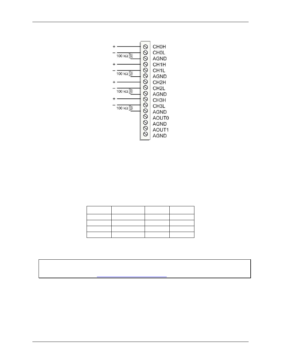
Figure 4 shows DIFF channels 0-3 connected to a ground path resistor.
Figure 4. DIFF connections with ground path resistor
Channel-Gain queue
The channel-gain queue feature allows you to configure a list of channels, modes, and gains for each scan. The
settings are stored in a channel-gain queue list that is written to local memory on the device.
The channel-gain queue list contains one or more channel numbers, modes, and range settings. You can
configure up to 16 elements. The channels can be listed in any order, and can include duplicate channels for
sampling at different ranges.
An example of a 4-element list is shown in the table below.
Sample channel gain queue list
Element
Channel
Range
Mode
0
CH5
BIP5V
SE
1
CH1
BIP10V
SE
2
CH15
BIP1V
SE
3
CH5
BIP5V
SE
Carefully match the gain to the expected voltage range on the associated channel or an over range condition
may occur. Although this condition does not damage the device, it does produce a useless full-scale reading,
and can introduce a long recovery time due to saturation of the input channel.
For more information about analog signal connections
For more information about analog input connections, refer to the Guide to Signal Connections (this document
is available on our web site at
Analog output
The two 16-bit analog outputs (
AOUT0
and
AOUT1
) can be updated simultaneously at a rate of 250 kS/s per
channel. One output can be updated at a rate of 500 kS/s. The output range is fixed at ±10 V. The outputs
default to 0 V when the host computer is shut down or suspended, or when a reset command is issued to the
device.