Signal connections, Analog input, Floating voltage source – Measurement Computing USB-1608GX-2AO-OEM User Manual
Page 12
USB-1608GX-2AO-OEM User's Guide
Functional Details
12
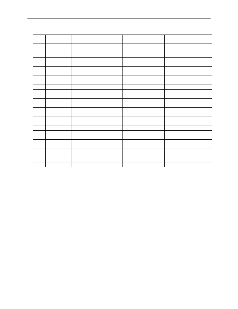
Single-ended mode pinout
Pin
Signal Name
Description
Pin
Signal Name
Description
1
CH0
Channel 0
29
CH15
Channel 15
2
CH8
Channel 8
30
CH7
Channel 7
3
AGND
Analog ground
31
AGND
Analog ground
4
CH1
Channel 1
32
CH14
Channel 14
5
CH9
Channel 9
33
CH6
Channel 6
6
AGND
Analog ground
34
AGND
Analog ground
7
CH2
Channel 2
35
CH13
Channel 13
8
CH10
Channel 10
36
CH5
Channel 5
9
AGND
Analog ground
37
AGND
Analog ground
10
CH3
Channel 3
38
CH12
Channel 12
11
CH11
Channel 11
39
CH4
Channel 4
12
AGND
Analog ground
40
AGND
Analog ground
13
AOUT0
Analog output 0
41
AGND
Analog ground
14
AGND
Analog ground
42
AGND
Analog ground
15
AOUT1
Analog output 1
43
+5V
+5V output
16
AGND
Analog ground
44
AGND
Analog ground
17
NC
No connection
45
NC
No connection
18
GND
Digital ground
46
GND
Digital ground
19
DIO0
Digital input/output 0
47
AICKI
AI clock input
20
DIO1
Digital input/output 1
48
AICKO
AI clock output
21
DIO2
Digital input/output 2
49
AOCKI
AO clock input
22
DIO3
Digital input/output 3
50
AOCKO
AO clock output
23
DIO4
Digital input/output 4
51
TRIG
Trigger input
24
DIO5
Digital input/output 5
52
GND
Digital ground
25
DIO6
Digital input/output 6
53
CTR1
Counter 1
26
DIO7
Digital input/output 7
54
CTR0
Counter 0
27
GND
Digital ground
55
TMR
Timer output
28
GND
Chassis ground
56
GND
Digital ground
Signal connections
Analog input
You can configure the analog inputs for SE or DIFF mode. The input voltage range is software selectable for
±10 V, ±5 V, ±2 V, or ±1 V.
With SE mode, connect up to 16 inputs to
CH0
to
CH15
. SE mode requires two wires:
Connect one wire to the signal you want to measure (
CHx
).
Connect one wire to the analog ground reference (
AGND
).
With DIFF mode, connect up to eight differential inputs to
CH0H/CH0L
to
CH7H/CH7L
. DIFF mode requires
two wires plus a ground reference:
Connect one wire to the high/positive signal (
CHxH
).
Connect one wire to the low/negative signal (
CHxL
).
Connect one wire to the analog ground reference (
AGND
).
Floating voltage source
When connecting DIFF voltage inputs to a "floating" voltage source, make sure the DIFF input channel has a
DC return path to ground. To create this path, connect a resistor from each low channel input to an AGND pin.
A value of approximately 100
kΩ can be used for most applications.
Leave unused input channels either floating or tied to an AGND terminal. Source impedances should be kept as
small as possible to avoid settling time and accuracy errors.