Board components, Usb connector, Leds – Measurement Computing USB-1608GX-2AO-OEM User Manual
Page 10: Header connectors
USB-1608GX-2AO-OEM User's Guide
Functional Details
10
Board components
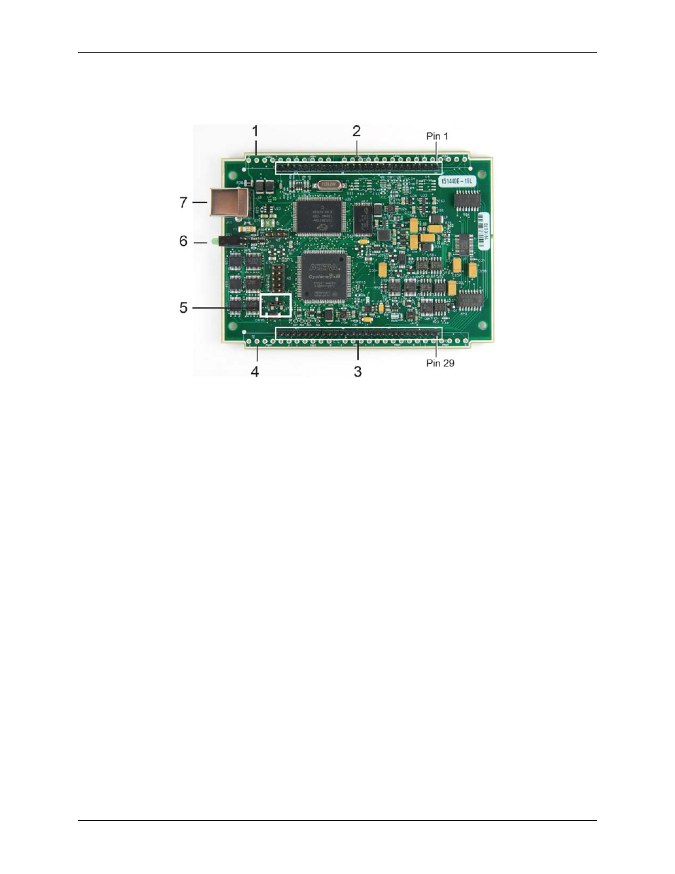
Board components are shown in Figure 3. Note that each screw terminal location is unpopulated.
1
Screw terminal (unpopulated)
5
Pull-up/down jumper W1
2
Header connector W4
6
Status LED (top) and Activity LED (bottom)
3
Header connector W6
7
USB connector
4
Screw terminal (unpopulated)
Figure 3. USB-1608GX-2AO-OEM external components
USB connector
The USB connector provides +5 V power and communication. No external power supply is required.
LEDs
The device has two LEDs –
Status
and
Activity
.
The
Status
LED turns on when the device is detected and installed on the computer.
The
Activity
LED blinks when data is transferred, and is off otherwise.
Figure 3 shows the location of each LED.
Header connectors
The header connectors provide the following connections:
16 SE (
CH0
to
CH15
) or eight DIFF (
CH0H/CH0L
to
CH7H/CH7L
) analog input connections
Eight digital I/O connections (
DIO0
to
DIO7
)
Two analog output connections (
AOUT0
,
AOUT1
)
One external clock input (
AICKI
) and one external clock output (
AICKO
) for analog inputs
One external clock input (
AOCKI
) and one external clock output (
AOCKO
) for analog outputs
One digital trigger input (
TRIG
)
Two counter inputs (
CTR0
,
CTR1
)
One timer output (
TMR
)
One power output (
+5V
)
13 analog ground (
AGND
) and five digital ground (
GND
) connections
The differential mode pinout is shown on page 11. The single-ended mode pinout is shown on page 12.