Counter input, Trigger input, Sync i/o – Measurement Computing USB-1608FS User Manual
Page 13: Calibration output
USB-1608FS User's Guide
13
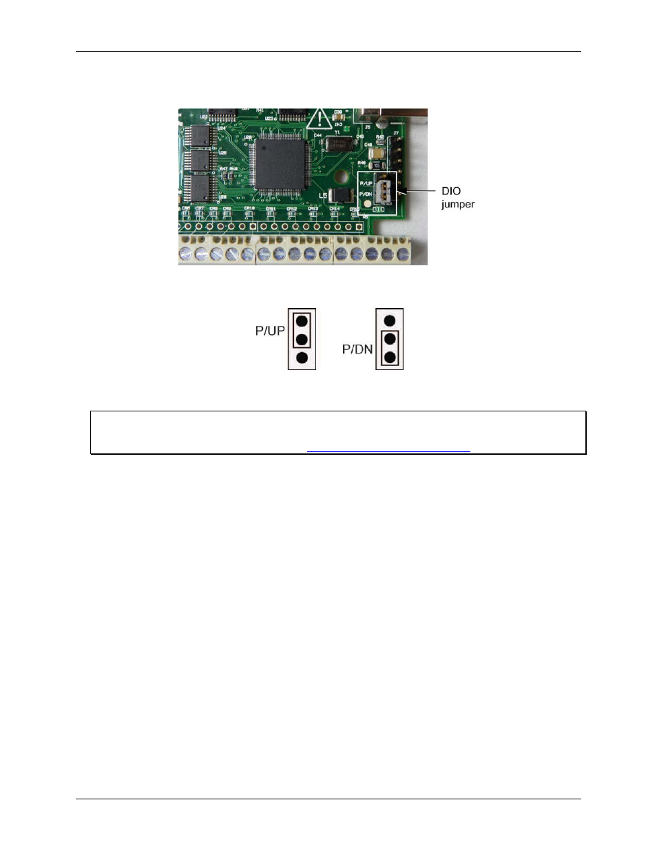
The user-configurable jumper is labeled
DIO
. Figure 5 shows the location of the jumper on the circuit
board.
Figure 5. Pull-up/down jumper location
5.
Configure the jumper for pull-up or pull-down, as shown in Figure 6.
Figure 6. Pull-up/down jumper configuration
6.
Replace the top section of the housing, and fasten it to the bottom section with the three screws.
For more information on digital signal connections
For general information regarding digital signal connections and digital I/O techniques, refer to the Guide to
Signal Connections (available on our web sit
Counter input
The
CTR
terminal is a 32-bit event counter that can accept frequency inputs up to 1 MHz. The internal counter
increments when the TTL levels transition from low to high.
Trigger input
The
TRIG_IN
terminal is an external digital trigger input. The trigger mode is set for edge sensitive, and is
configurable for rising or falling edge. On power up and reset the trigger mode is set for rising edge.
SYNC I/O
The
SYNC
terminal is a bidirectional I/O signal that can be configured as an input (default) or an output.
Configure as an external clock input to externally source the A/D conversions. The SYNC terminal
supports TTL-level input signals of up to 50 kHz.
Configure as an output to pace conversions on a second USB-1608FS device and acquire data from
16 channels. For more information about synchronized operations see page 17.
Calibration output
The
CAL
terminal is an output that is used to calibrate the USB-1608FS. Do not use this pin for any other
purpose. Calibration is software-controlled by InstaCal.