Signal connections, Analog input – Measurement Computing USB-1608FS User Manual
Page 11
USB-1608FS User's Guide
11
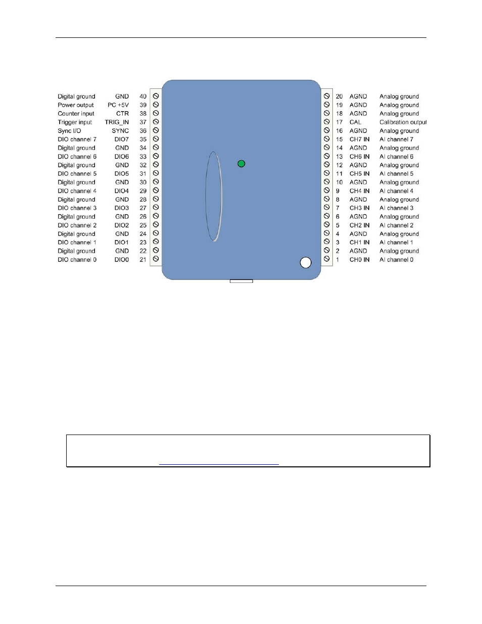
Use 16 AWG to 30 AWG wire when making connections to the screw terminals. Pinout locations are shown in
Figure 3 below.
Figure 3. Screw terminal pinout
Signal connections
Analog input
You can connect up to eight analog input connections to
CH0 IN
through
CH7 IN
. Connect unused analog input
terminals to ground terminals during operation. For example, if you are not using terminal 15 (
CH7 IN
), connect
this terminal to terminal 16 (
AGND
).
The analog input channels are configured for single-ended input mode. Each analog signal is referenced to
signal ground (AGND), and requires two wires:
Connect the wire carrying the signal to be measured to
CH# IN
.
Connect the second wire to
AGND
.
The input voltage ranges are ±10 V, ±5 V, ±2.0 V, ±1.0 V.
For more information on analog signal connections
For more information on single-ended inputs, refer to the Guide to Signal Connections (this document is
available on our web site at
- ACC-300 (7 pages)
- AI-EXP32 (20 pages)
- AI-EXP48 (19 pages)
- BTH-1208LS (30 pages)
- 6K-ERB08 (32 pages)
- BTH-1208LS Quick Start (4 pages)
- 6K-SSR-RACK08 (33 pages)
- BTH-1208LS-OEM (27 pages)
- CB-COM-Digital (68 pages)
- CB-7018 (68 pages)
- CB-7000 Utilities (44 pages)
- CB-7080D (74 pages)
- CB-COM-7033 (44 pages)
- CB-COM-7017 (72 pages)
- CB-COM-7024 (76 pages)
- CB-NAP-7000P (36 pages)
- CIO-DAC02/16 (16 pages)
- CIO-DAC02 (18 pages)
- CB-NAP-7000D (56 pages)
- CIO-DAC16-I (16 pages)
- CIO-DAC16/16 (20 pages)
- CIO-DAS08 (21 pages)
- CIO-DAC16 (20 pages)
- CIO-DAS08/JR (16 pages)
- CIO-DAS08/JR/16 (14 pages)
- CIO-DAS08/JR-AO (16 pages)
- CIO-DAS08-AOM (32 pages)
- CIO-DAS08-PGM (28 pages)
- CIO-DAS16/330 (34 pages)
- CIO-DAS48-I (17 pages)
- CIO-DAS16/M1 (38 pages)
- CIO-DAS48-PGA (18 pages)
- CIO-DAS800 (20 pages)
- CIO-DAS802/16 (22 pages)
- CIO-DAS6402/16 (40 pages)
- CIO-DAS-TEMP (20 pages)
- CIO-DDA06/16 (18 pages)
- CIO-DDA06/JR (17 pages)
- CIO-DIO24/CTR3 (21 pages)
- CIO-DIO24H (20 pages)
- CIO-DI192 (24 pages)
- CIO-DDA06 (21 pages)
- CIO-DIO48 (19 pages)
- CIO-DO192H (16 pages)
- CIO-DIO192 (20 pages)