Digital i/o, Pull-up/down configuration – Measurement Computing USB-1608FS-Plus User Manual
Page 12
USB-1608FS-Plus User's Guide
Functional Details
12
Carefully match the gain to the expected voltage range on the associated channel or an over range condition
may occur. Although this condition does not damage the device, it does produce a useless full-scale reading,
and can introduce a long recovery time due to saturation of the input channel.
Digital I/O
You can connect up to eight digital I/O lines to
DIO0
through
DIO7
. Each digital channel is individually
configurable for input or output. During initial power on or reset the digital pins are set for input.
The digital I/O terminals can detect the state of any TTL-level input. Refer to the schematic shown in Figure 4.
Figure 4. Schematic showing switch detection by digital channel DIO0
If you set the switch to the +5 V input, DIO0 reads TRUE (1). When set to GND, DIO0 reads FALSE (0).
Pull-up/down configuration
All digital I/O lines are pulled up to USB +5V (HI) with a 47 kΩ resistor (default). You can change the
pull-up/down configuration using the internal jumper labeled
DIO
. You must remove the device housing to
access the jumper on the circuit board.
To set the jumper for pull-up or pull-down, complete the following steps.
1. Unplug the device from the computer.
2. Turn the device over and rest the top of the housing on a flat, stable surface.
Caution! The discharge of static electricity can damage some electronic components. Before removing the
USB-1608FS-Plus from its housing, ground yourself using a wrist strap or touch the computer
chassis or other grounded object to eliminate any stored static charge.
3. Remove the three screws from the bottom of the device using a #1 Philips head screwdriver.
4. Hold both the top and bottom sections together, turn the device over and rest it on the surface, then
carefully remove the top section of the case to expose the circuit board.
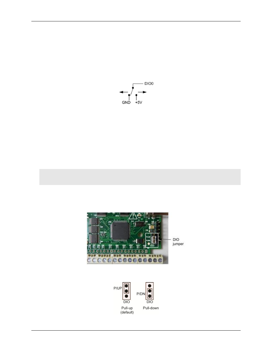
Figure 5 shows the location of the
DIO
jumper on the circuit board.
Figure 5. Pull-up/down jumper location
5. Configure the jumper for pull-up or pull-down, as shown in Figure 6.
Figure 6. Pull-up/down jumper configuration