Signal connections, Analog input, Channel-gain queue – Measurement Computing USB-1608FS-Plus User Manual
Page 11
USB-1608FS-Plus User's Guide
Functional Details
11
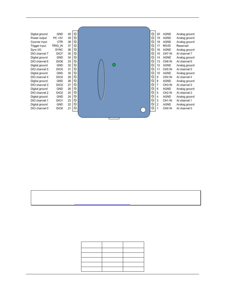
Figure 3. Screw terminal pinout
Signal connections
Analog input
You can connect up to eight analog input connections to the screw terminal containing pins 1 to 20 (
CH0 IN
through
CH7 IN
.) Connect unused analog input terminals to ground terminals during operation. For example, if
you are not using terminal 15 (
CH7 IN
), connect this terminal to terminal 16 (
AGND
).
All analog input channels are configured for single-ended input mode. All analog input signals are referenced to
ground (
AGND
):
Connect the wire carrying the signal to be measured to
CH# IN
.
Connect the second wire to
AGND
.
The input voltage ranges are ±10 V, ±5 V, ±2.0 V, ±1.0 V.
For more information on analog signal connections
For more information on single-ended inputs, refer to the Guide to Signal Connections (this document is
available on our web site
Channel-Gain queue
The channel-gain queue feature allows you to configure a different gain setting for each channel. The gain
settings are stored in a channel-gain queue list that is written to local memory on the device.
The channel-gain queue list can contain up to eight unique elements. The channel list must be in increasing
order. An example of a five element list is shown in the table below.
Sample channel-gain queue list
Element
Channel
Range
0
CH0
BIP1V
1
CH2
BIP2V
2
CH4
BIP10V
3
CH6
BIP1V
4
CH7
BIP5V