Counter input, Timer output, Ee figure 9 – Measurement Computing USB-1208HS-4AO User Manual
Page 14: Figure 10)
USB-1208HS-4AO User's Guide
Functional Details
14
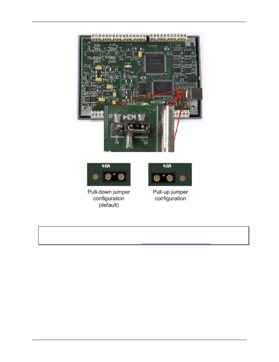
Figure 9. Location of W34 jumper (default pull-down setting shown)
Figure 10. Pull-down and pull-up configurations
1. Replace the top section of the case, and then fasten it to the bottom section with the four screws.
For more information on digital signal connections
For general information regarding digital signal connections and digital I/O techniques, refer to the Guide to
DAQ Signal Connections (available on our web site at
Counter input
CTR0
and
CTR1
provide connections to each 32-bit counter input channel. Each counter can count frequencies
of up to 20 MHz.
Timer output
Use the
TMR
terminal to connect to the pulse width modulation (PWM) timer output. You can set the following
timer output parameters through software:
pulse frequency
duty cycle (pulse width divided by the pulse period)
number of pulses to generate
time delay before starting the timer output after it's enabled
resting state of the output (idle high or idle low)
The timer can generate a pulse output with a programmable frequency range of 0.00931 Hz up to 20 MHz.