Specifications, Analog input, Accuracy – Measurement Computing USB-205 User Manual
Page 14: Analog input dc voltage measurement accuracy, Chapter 4
14
Chapter 4
Specifications
All specifications are subject to change without notice.
Typical for 25 °C unless otherwise specified.
Specifications in italic text are guaranteed by design.
Analog input
Table 1. General analog input specifications
Parameter
Condition
Specification
A/D converter type
Successive approximation
ADC resolution
12 bits
Number of channels
8 single-ended
Input voltage range
±10 V
Absolute maximum input
voltage
CHx relative to AGND
±25 V max (power on)
±25 V max (power off)
Input impedance
1 MΩ (power on)
1 MΩ (power off)
Input bias current
10 V input
–12 µA
0 V input
2 µA
–10 V input
12 µA
Input bandwidth
Small signal (–3 dB)
1.0 MHz
Maximum working voltage
Input range relative to
AGND
±10.1 V max
Crosstalk
Adjacent channels, DC to
10 kHz
–75 dB
Input coupling
DC
Sampling rate
Internal pacer
0.016 S/s to 500 kS/s, software-selectable
External pacer
500 kS/s max
Sample clock source
Internal A/D clock
Pacer input terminal AICKI
Channel queue
Up to eight unique, ascending channels
Throughput
Software paced
33 S to 4,000 S/s typ, system dependent
Hardware paced
500 kS/s max, system dependent
Warm-up time
15 minutes min
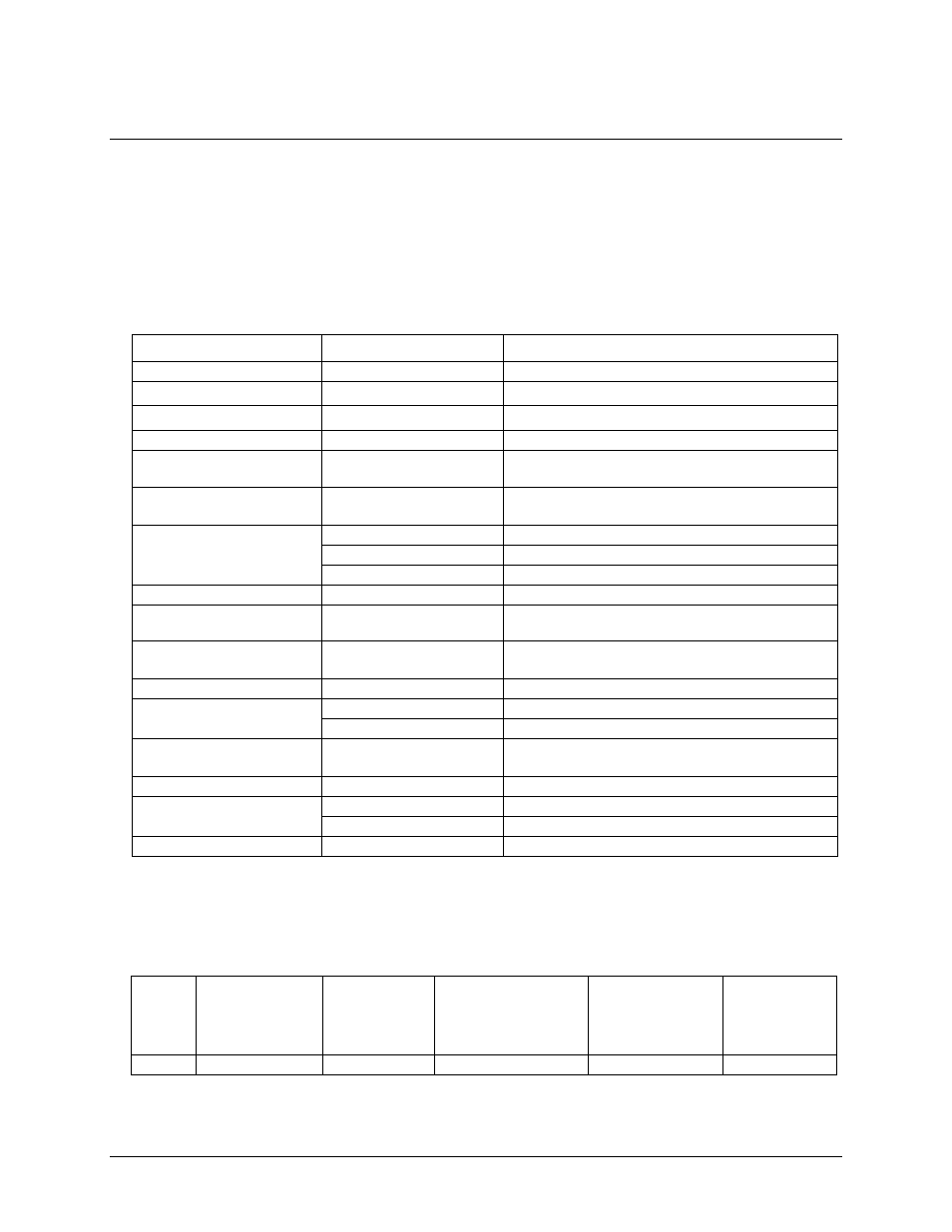
Accuracy
Analog input DC voltage measurement accuracy
Table 2. DC Accuracy components and specifications. All values are (±)
Range
Gain error
(% of reading)
Offset error
(mV)
Absolute accuracy
at Full Scale
(mV)
Gain temperature
coefficient
(% reading/°C)
Offset
temperature
coefficient
(mV/°C)
±10V
0.098
11
20.8
0.016
0.87