Signal connections, Analog input, External clock i/o – Measurement Computing USB-205 User Manual
Page 10: Analog output, Digital i/o, Pull-up/down jumper w4
USB-205 User's Guide
Functional Details
10
Signal connections
Analog input
You can connect up to 8 single-ended inputs to screw terminals
CH0
to
CH7
. The input voltage range is ±10 V.
Single-ended mode requires two wires; connect one wire to the signal you want to measure (
CHx
), and connect
a second wire to the analog ground reference (
AGND
).
External clock I/O
The USB-205 provides one external clock input (
AICKI
) and one clock output (
AICKO
) for the analog input
pacer. Connect the external clock signal to
AICKI
.
When using an external clock,
AICKO
outputs the pulse generated from
AICKI
.
When using the internal clock,
AICKO
outputs the
ADC scan clock.
Analog output
The USB-205 has two 12-bit analog outputs (
AOUT0
and
AOUT1
). Both outputs can be updated simultaneously
at a rate of 125 S/s per channel. One output can be updated at a rate of 250 S/s. The output range is fixed at 0 V
to 5 V. The outputs default to 0 V when the host computer is shut down or suspended, or when a reset command
is issued to the device.
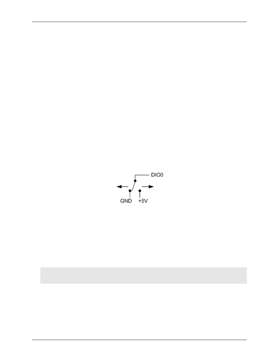
Digital I/O
You can connect up to eight digital I/O lines to
DIO0
through
DIO7
. The digital I/O terminals can detect the
state of any TTL-level input. Refer to the schematic shown in Figure 4.
Figure 4. Schematic showing switch detection by digital channel DIO0
If you set the switch to the +5 V input, DIO0 reads TRUE (1). If you move the switch to GND, DIO0 reads
FALSE (0).
Pull-up/down jumper W4
The digital port has 47 kΩ resistors that you can configure as pull-up or pull-down with the internal jumper
labeled
W4
. Unconnected inputs are pulled low by default to 0 V through 47 kΩ resistors. The pull-up/pull-
down voltage is common to all 47 kΩ resistors.
You must remove the cover from the device in order to access the jumper. To remove the cover, unscrew the
four screws on the device bottom.
Caution! The discharge of static electricity can damage some electronic components. Before removing the
device from its housing, either ground yourself using a wrist strap or touch the computer chassis or
other grounded object to eliminate any stored static charge.