Trigger input, Counter input, Voltage output – Measurement Computing USB-205 User Manual
Page 11: Ground
USB-205 User's Guide
Functional Details
11
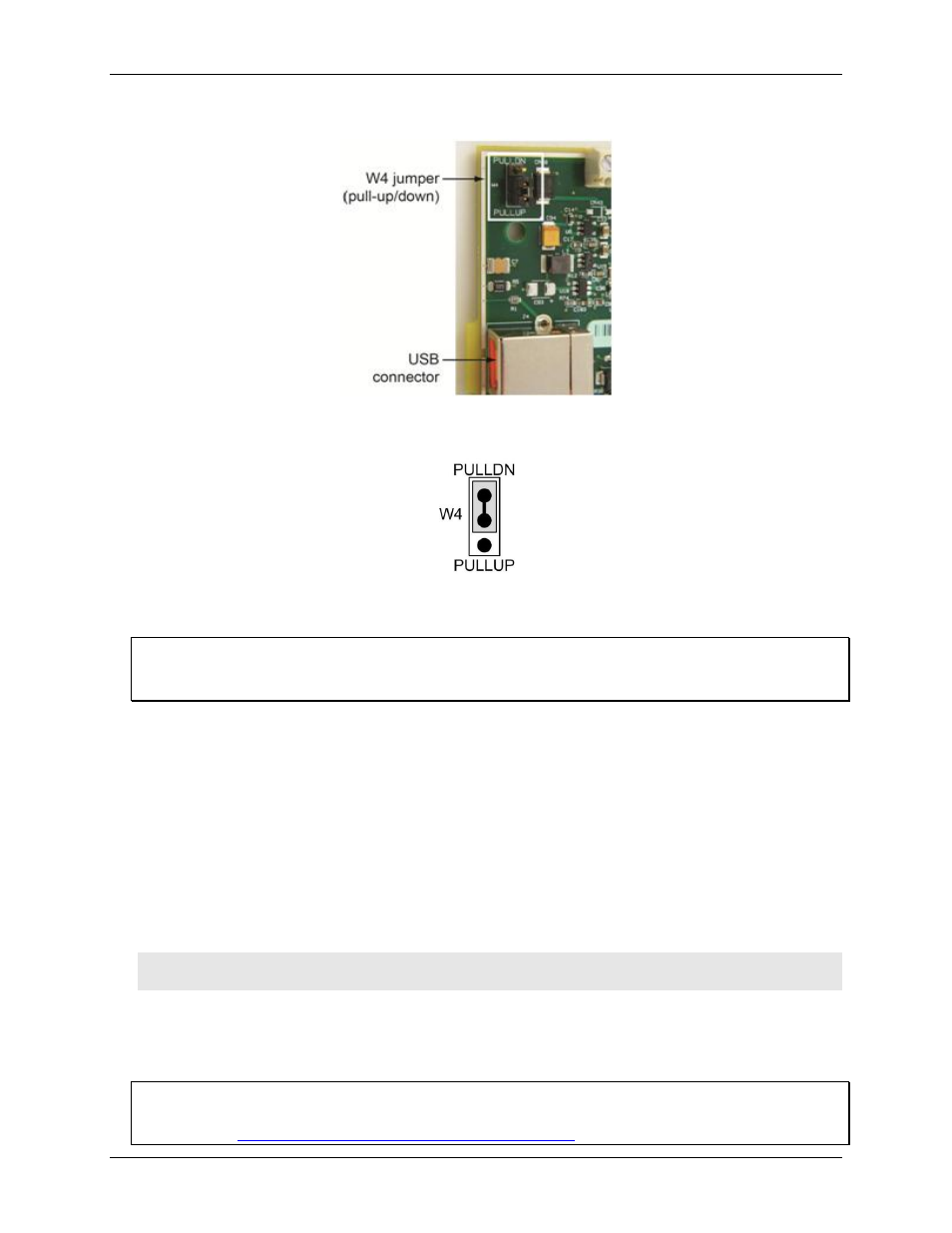
Figure 5 shows the location of jumper W4 in relation to the USB connector.
Figure 5. Jumper W4 location
Jumper W4 is configured by default for pull-down; see Figure 6.
Figure 6. Jumper W4 pull-up/down configuration
To pull the digital inputs high (+5V), configure the jumper for pull-up.
Proper LED alignment
When placing the circuit board within the housing, align the board LEDs with the top of the housing before
attaching the housing bottom.
Trigger input
The
TRIG
terminal is an external digital trigger input. The trigger mode is software-selectable for edge- or
level-sensitive.
Counter input
The
CTR
terminal is a 32-bit event counter that can accept frequency inputs up to 1 MHz. The internal counter
increments when the TTL levels transition from low to high.
Voltage output
The user voltage output
(+VO)
terminal can output up to 100 mA maximum at approximately +5V. You can use
this terminal to supply power to external devices or circuitry.
Caution! The
+VO
terminal is an output. Do not connect to an external power supply or you may damage
the device and possibly the computer.
Ground
The analog ground (
AGND
) terminals provide a common ground for all analog channels. The digital ground
(
GND
) terminals provide a common ground for the digital, counter, pacer I/O, and power terminal.
For more information about signal connections
For more information about analog and digital signal connections, refer to the Guide to DAQ Signal
Connections