Screw terminal connector (not populated) – Measurement Computing USB-202-OEM User Manual
Page 20
USB-202-OEM User's Guide
Specifications
20
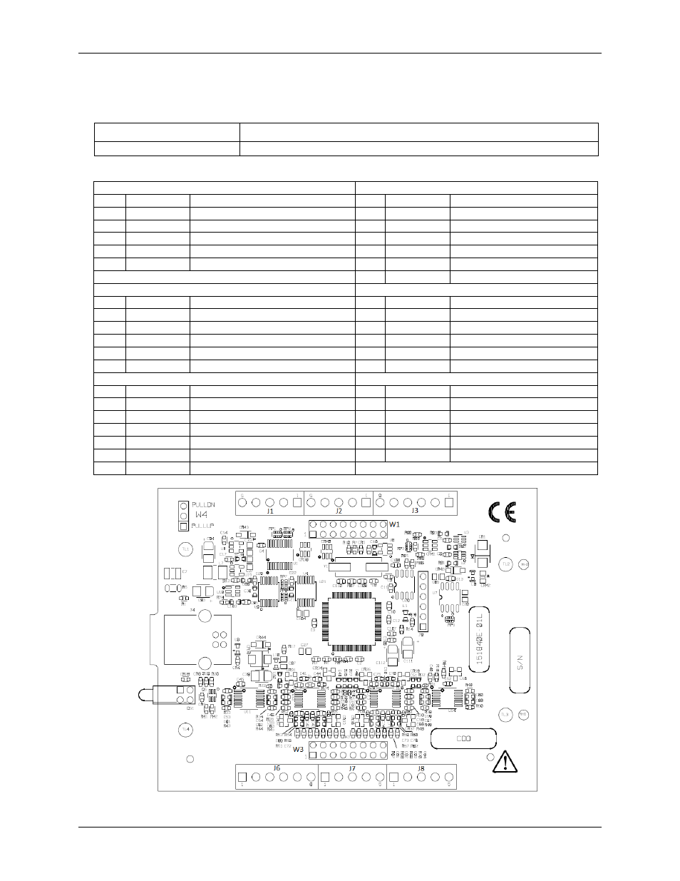
Screw terminal connector (not populated)
Table 20. Screw terminal connector specifications
Parameter
Specification
Connector type
3.51mm screw terminal footprints (not populated), labeled J1, J2, J3, J6, J7, J8
Table 21. Screw terminal pinout
J1
J6
Pin
Signal name
Pin description
Pin
Signal name
Pin description
5
DIO0
DIO bit 0
1
CH0
Channel 0
4
DIO1
DIO bit 1
2
CH1
Channel 1
3
DIO2
DIO bit 2
3
AGND
Analog ground
2
DIO3
DIO bit 3
4
CH2
Channel 2
1
DIO4
DIO bit 4
5
CH3
Channel 3
6
AGND
Analog ground
J2
J7
Pin
Signal name
Pin description
Pin
Signal name
Pin description
5
DIO5
DIO bit 5
1
CH4
Channel 4
4
DIO6
DIO bit 6
2
CH5
Channel 5
3
DIO7
DIO bit 7
3
AGND
Analog ground
2
GND
Digital ground
4
CH6
Channel 6
1
+VO
User voltage output
5
CH7
Channel 7
J3
J8
Pin
Signal name
Pin description
Pin
Signal name
Pin description
6
GND
Digital ground
1
AGND
Analog ground
5
AICKO
External clock pacer output
2
AOUT0
Analog output 0
4
AICKI
External clock pacer input
3
AGND
Analog ground
3
CTR
Counter input
4
AOUT1
Analog output 1
2
TRIG
Digital trigger input
5
AGND
Analog ground
1
GND
Digital ground