Digital i/o, Pull-up/down jumper w4, Trigger input – Measurement Computing USB-202-OEM User Manual
Page 12: Counter input, Voltage output, Ground
USB-202-OEM User's Guide
Functional Details
12
Digital I/O
You can connect up to eight digital I/O lines to
DIO0
through
DIO7
. The digital I/O terminals can detect the
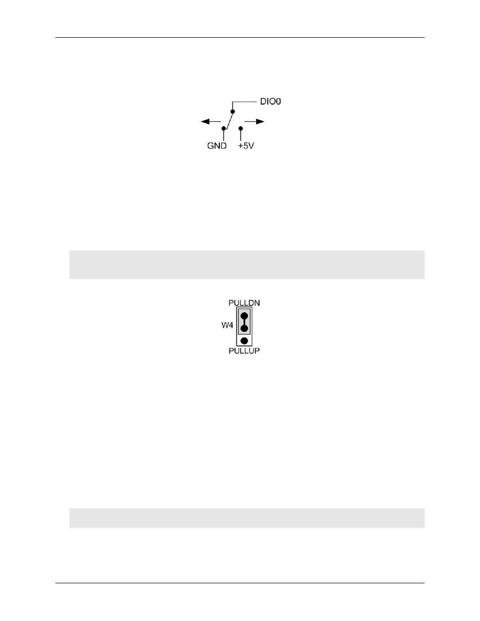
state of any TTL-level input. Refer to the schematic shown in Figure 5.
Figure 5. Schematic showing switch detection by digital channel DIO0
If you set the switch to the +5 V input, DIO0 reads TRUE (1). If you move the switch to GND, DIO0 reads
FALSE (0).
Pull-up/down jumper W4
The digital port has 47
kΩ resistors that you can configure as pull-up or pull-down with jumper
W4
2 on page 10 for the location of this jumper).
Unconnected inputs are pulled low by default to 0 V through 47
kΩ resistors. The pull-up/pull-down voltage is
common to all 47
kΩ resistors.
Caution! The discharge of static electricity can damage some electronic components. Before handling the
board, either ground yourself using a wrist strap or touch the computer chassis or other grounded
object to eliminate any stored static charge.
Jumper W4 is configured by default for pull-down; see Figure 6.
Figure 6. Jumper W4 pull-up/down configuration
To pull the digital inputs high (+5V), configure the jumper for pull-up.
Trigger input
The
TRIG
terminal is an external digital trigger input. The trigger mode is software-selectable for edge- or
level-sensitive.
Counter input
The
CTR
terminal is a 32-bit event counter that can accept frequency inputs up to 1 MHz. The internal counter
increments when the TTL levels transition from low to high.
Voltage output
The user voltage output
(+VO)
terminal can output up to 100 mA maximum at approximately +5V. You can use
this terminal to supply power to external devices or circuitry.
Caution! The
+VO
terminal is an output. Do not connect to an external power supply or you may damage
the device and possibly the computer.
Ground
The analog ground (
AGND
) terminals provide a common ground for all analog channels. The digital ground
(
GND
) terminals provide a common ground for the digital, counter, pacer I/O, and power terminal.