Board components, Connector w1 – Measurement Computing USB-202-OEM User Manual
Page 10
USB-202-OEM User's Guide
Functional Details
10
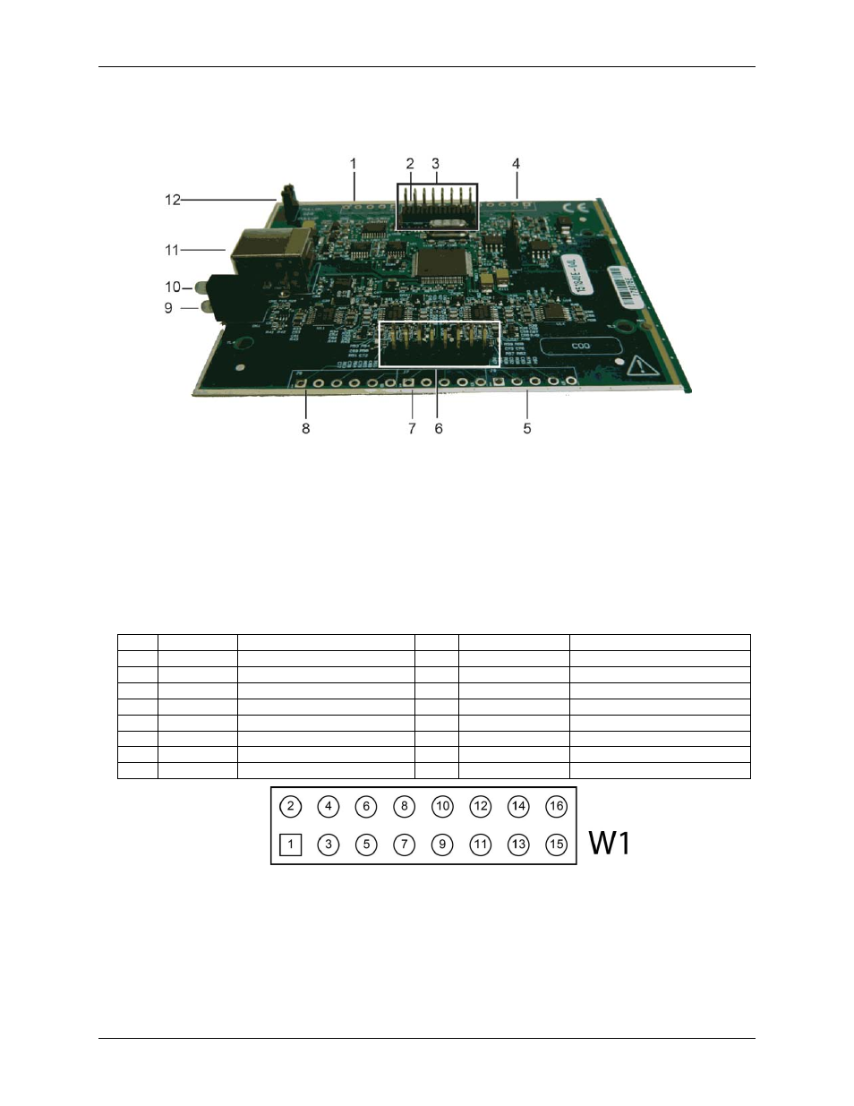
Board components
Board components are shown in Figure 2. Note that each screw terminal location is unpopulated.
1
Screw terminal J1
5
Screw terminal J8
9
Activity LED
2
Screw terminal J2
6
Header connector W3
10
Status LED
3
Header connector W1
7
Screw terminal J7
11
USB connector
4
Screw terminal J3
8
Screw terminal J6
12
Pull-up/down jumper W4
Figure 2. Board components
Connector W1
Header connector W1 provides connections for the DIO, external clock I/O, trigger, counter, power output, and
digital ground reference.
W1 pinout
Pin
Signal name
Pin description
Pin
Signal name
Pin description
1
DIO0
DIO channel 0
2
DIO1
DIO channel 1
3
DIO2
DIO channel 2
4
DIO3
DIO channel 3
5
DIO4
DIO channel 4
6
DIO5
DIO channel 5
7
DIO6
DIO channel 6
8
DIO7
DIO channel 7
9
GND
Digital ground
10
+VO
User voltage output
11
GND
Digital ground
12
AICKO
External clock pacer output
13
AICKI
External clock pacer input
14
CTR
Counter input
15
TRIG
Digital trigger input
16
GND
Digital ground
Figure 3. Connector W1 pinout