Connector w3, Screw terminal connectors, Usb connector – Measurement Computing USB-202-OEM User Manual
Page 11: Led indicators, Signal connections, Analog input, External pacer i/o, Analog output
USB-202-OEM User's Guide
Functional Details
11
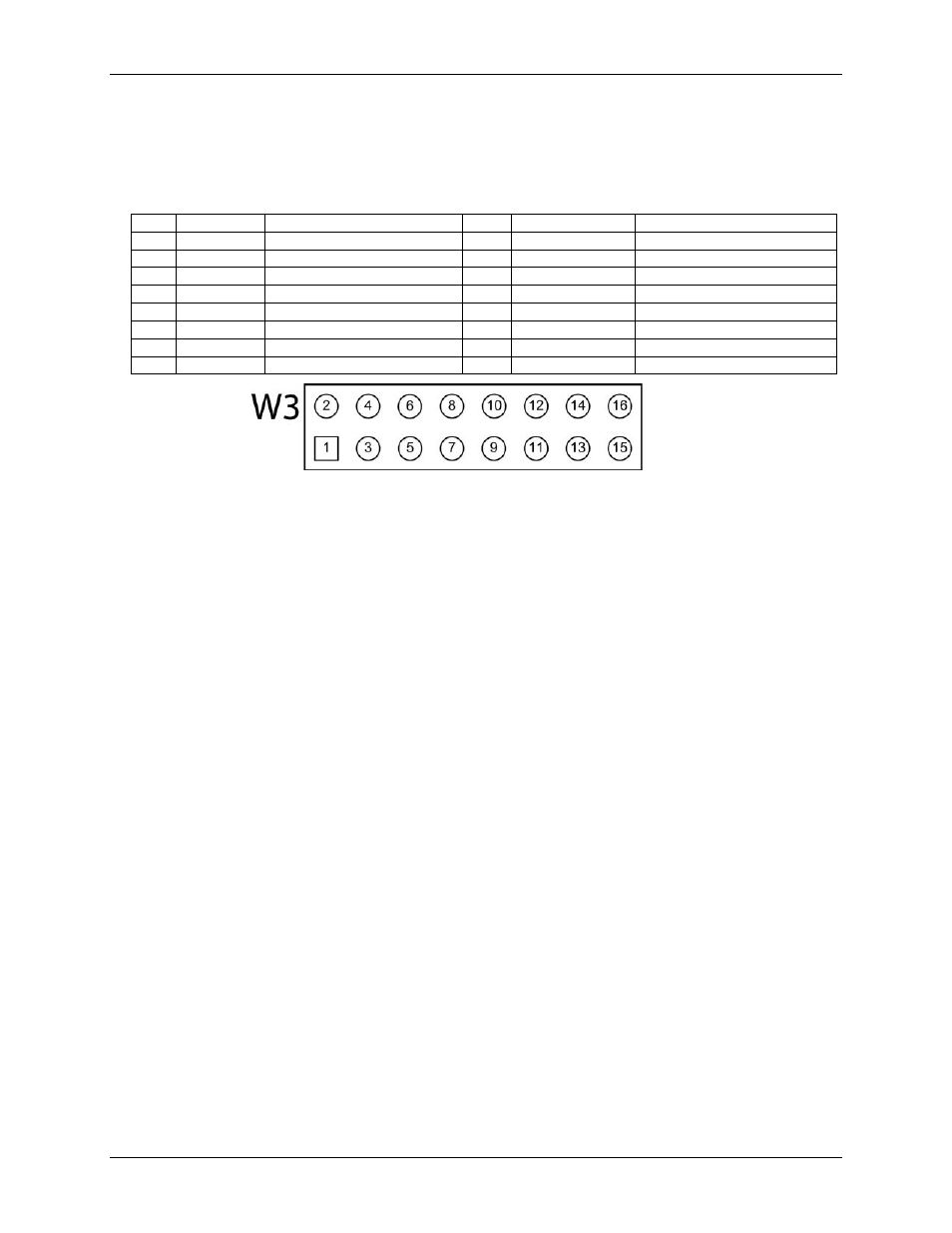
Connector W3
Header connector W3 provides connections for the analog inputs, analog outputs, and the analog ground
reference.
W3 pinout
Pin
Signal name
Pin description
Pin
Signal name
Pin description
1
CH0
Channel 0
2
CH1
Channel 1
3
AGND
Analog ground
4
CH2
Channel 2
5
CH3
Channel 3
6
AGND
Analog ground
7
CH4
Channel 4
8
CH5
Channel 5
9
AGND
Analog ground
10
CH6
Channel 6
11
CH7
Channel 7
12
AGND
Analog ground
13
AOUT0
Analog output 0
14
AGND
Analog ground
15
AOUT1
Analog output 1
16
AGND
Analog ground
Figure 4. Connector W3 pinout
Screw terminal connectors
Screw terminals J1 through J8 are unpopulated. When populated the screw terminals provide alternative
connections to the header connectors. Refer to the Specifications chapter for screw terminal pinouts.
USB connector
The USB connector provides +5 V power and communication. No external power supply is required.
LED indicators
The device has two LED indicators –
Status
and
Activity.
The
Status
LED turns on when the device is detected and installed on the computer.
The
Activity
LED blinks when data is transferred, and is off otherwise.
Refer to Figure 2 on page 10 for the location of these LEDs.
Signal connections
Analog input
You can connect up to 8 single-ended inputs to screw terminals
CH0
to
CH7
. The input voltage range is ±10 V.
Single-ended mode requires two wires; connect one wire to the signal you want to measure (
CHx
), and connect
a second wire to the analog ground reference (
AGND
).
External pacer I/O
The USB-202-OEM provides one external clock input (
AICKI
) and one clock output (
AICKO
) for the analog
input pacer. You can connect an external clock signal to
AICKI
.
When using the internal clock,
AICKO
outputs the
ADC sample clock.
Analog output
The USB-202-OEM has two 12-bit analog outputs (
AOUT0
and
AOUT1
). Both outputs can be updated
simultaneously at a rate of 125 S/s per channel. One output can be updated at a rate of 250 S/s. The output range
is fixed at 0 V to 5 V. The outputs default to 0 V when the host computer is shut down or suspended, or when a
reset command is issued to the device.