Measurement Computing SWITCH AND SENSE 8/8 User Manual
Page 15
Switch & Sense 8/8 User's Guide Functional
Details
3-4
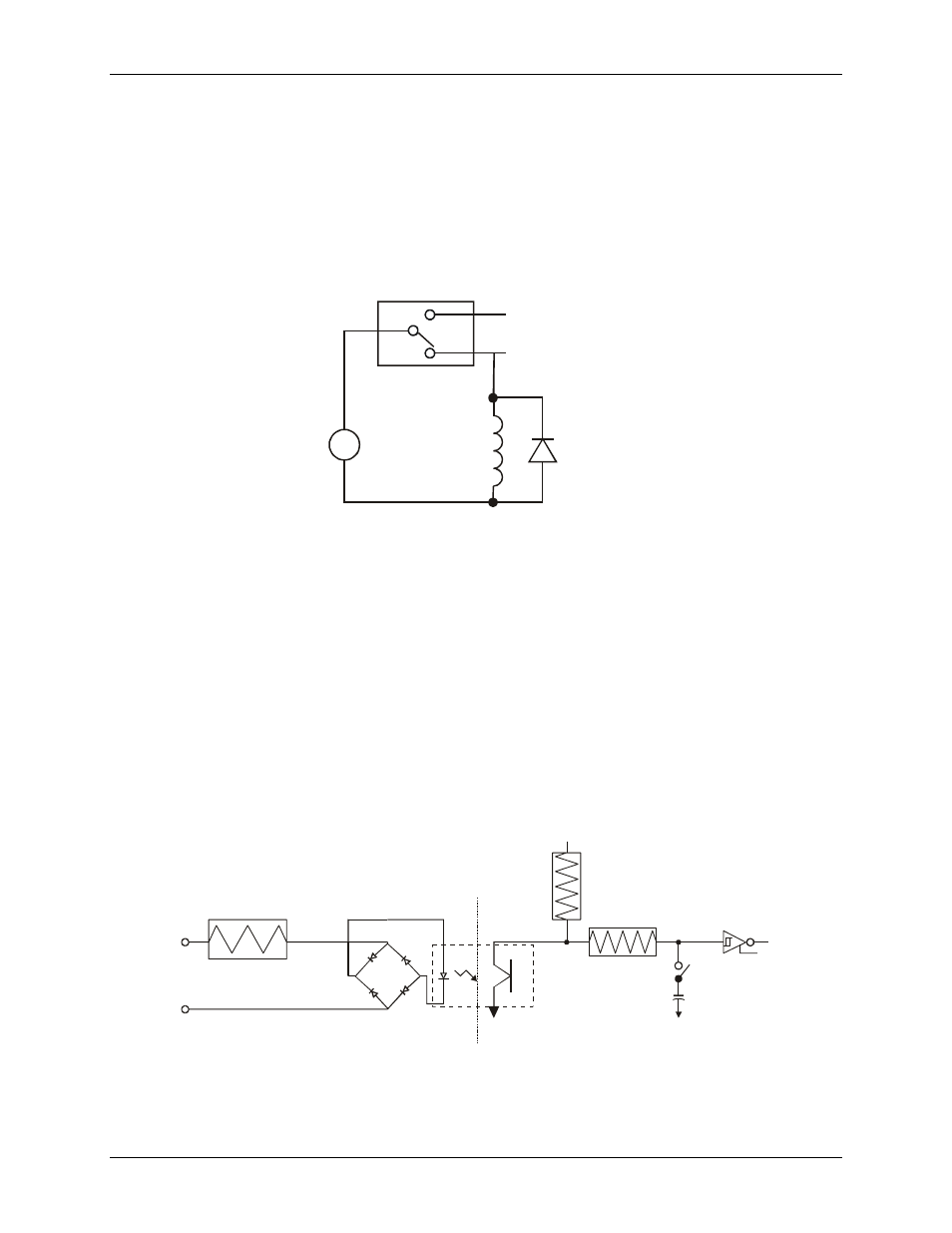
Relay contact protection circuit for inductive loads
If you are using the relays to control inductive loads, place a diode across the load terminals to suppress the
kickback voltage. If the diode is not present, the kickback voltage could cause the on-board processor to enter
an unstable state. To return the processor to a stable state, unplug the power cable from the Switch & Sense 8/8
and then reconnect.
A contact protection circuit is shown in Figure 3-4. For AC loads, install a metal oxide varistor (MOV).
C
V
Inductive
Load
Kickback
Diode
NC
+
-
NO
Relay
Figure 3-4. Relay contact protection circuit
Differential isolated digital input terminals (IP0A to IP7B)
Connect up to eight isolated digital input signals using the following screw terminal pairs:
!
IP0A and IP0B
!
IP4A and IP4B
!
IP1A and IP1B
!
IP5A and IP5B
!
IP2A and IP2B
!
IP6A and IP6B
!
IP3A and IP3B
!
IP7A and IP7B
A schematic of a single channel is shown in Figure 3-5. Each signal is applied to a bridge rectifier so that the
input is not polarity-sensitive. It can be driven by either AC (50 - 1000 Hz) or DC voltage.
The eight optically isolated (500 V) inputs can be read back as a single byte. Each input has a software-
controlled filter with a time constant of 5 ms (200 Hz). The filter is required for AC inputs, and recommended
for almost all DC inputs. Unless you have a good reason to turn off a filter, we recommend that you enable it.
1.6 K
Isolated Input
Not Polarized
Circuitry Sharing
PC Ground
Filter Switch
0.1uF
47K
+5V
100K
Figure 3-5. Switch & Sense 8/8 single-channel configuration