Main connector and pin out, Form c relay output, Main connector and pin out -3 – Measurement Computing SWITCH AND SENSE 8/8 User Manual
Page 14
Switch & Sense 8/8 User's Guide Functional
Details
3-3
Main connector and pin out
Table 3-2. Connector specifications
Connector type
Screw terminal
Wire gauge range
12 AWG to 20 AWG
Table 3-3. Screw terminal pin out
Pin
Signal Name
Pin
Signal Name
IP0A
Input 0 terminal A
IP4A
Input 4 terminal A
IP0B
Input 0 terminal B
IP4B
Input 4 terminal B
IP1A
Input 1 terminal A
IP5A
Input 5 terminal A
IP1B
Input 1 terminal B
IP5B
Input 5 terminal B
IP2A
Input 2 terminal A
IP6A
Input 6 terminal A
IP2B
Input 2 terminal B
IP6B
Input 6 terminal B
IP3A
Input 3 terminal A
IP7A
Input 7 terminal A
IP3B
Input 3 terminal B
IP7B
Input 7 terminal B
0-NO
Relay 0 Normally Open contact
4-NO
Relay 4 Normally Open contact
0-C
Relay 0 Common contact
4-C
Relay 4 Common contact
0-NC
Relay 0 Normally Closed contact
4-NC
Relay 4 Normally Closed contact
1-NO
Relay 1 Normally Open contact
5-NO
Relay 5 Normally Open contact
1-C
Relay 1 Common contact
5-C
Relay 5 Common contact
1-NC
Relay 1 Normally Closed contact
5-NC
Relay 5 Normally Closed contact
2-NO
Relay 2 Normally Open contact
6-NO
Relay 6 Normally Open contact
2-C
Relay 2 Common contact
6-C
Relay 6 Common contact
2-NC
Relay 2 Normally Closed contact
6-NC
Relay 6 Normally Closed contact
3-NO
Relay 3 Normally Open contact
7-NO
Relay 7 Normally Open contact
3-C
Relay 3 Common contact
7-C
Relay 7 Common contact
3-NC
Relay 3 Normally Closed contact
7-NC
Relay 7 Normally Closed contact
Relay contact terminals (NO, C, NC (0) to NO, C, NC (7))
The two outer groups of 12 screw terminals shown in Figure 3-2 connect to the normally open (NO), common
(C), and normally closed (NC) contacts for relays 0 through 7.
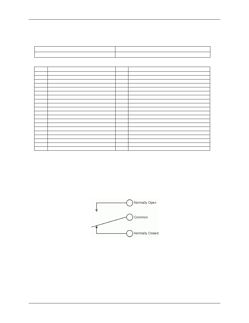
Form C relay output
A schematic for Form C relay contacts is shown in Figure 3-3. The Form C relay has a C, NO, and NC contact.
Figure 3-3. Form C SPDT relay
!
When a (0) is written to the output bit, the C and NC are in contact.
!
When a (1) is written to the output bit, the C and NO are in contact.
At power-up, the relays are put into a non-energized state (NC in contact to Common).