External power led, Status led, Usb connector – Measurement Computing SWITCH AND SENSE 8/8 User Manual
Page 13: Internal components, Screw terminals and relays, External power led -2, Status led -2, Usb connector -2, Internal components -2, Screw terminals and relays -2
Switch & Sense 8/8 User's Guide Functional
Details
3-2
External power LED
The LED labeled
EXTERNAL POWER
lights up when the Switch & Sense 8/8 is connected to an external
power source. It uses up to 5 mA of current and cannot be disabled.
Status LED
The LED labeled
STATUS
indicates the communication status of the Switch & Sense 8/8. It uses up to 5 mA of
current and cannot be disabled. Table 3-1 explains the function of the Switch & Sense 8/8 status LED.
Table 3-1. Status LED illumination
LED Illumination
Indication
Steady green
The Switch & Sense 8/8 is connected to a computer or external USB hub.
Blinks continuously
Data is being transferred.
Blinks three times
Initial communication is established between the Switch & Sense 8/8 and the computer.
USB connector
The USB connector on the back of the Switch & Sense 8/8 enclosure provides +5 V power and communication.
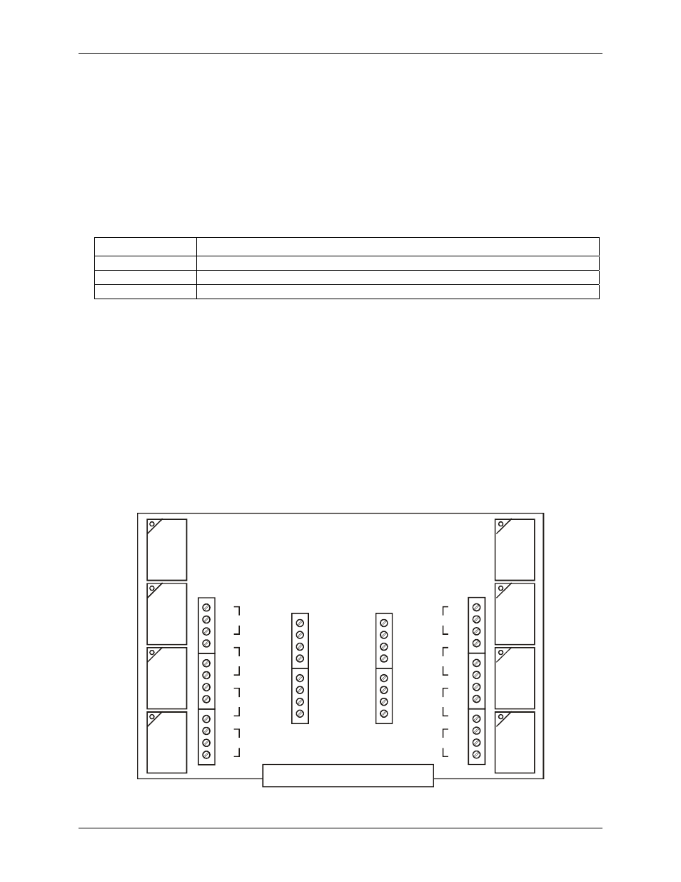
Internal components
Screw terminals and relays
The Switch & Sense 8/8 has four rows of screw terminals — two outer rows containing 12 terminals each, and
two inner rows containing eight terminals each.
!
The outer rows of terminals connect to the eight relays available from the Switch & Sense 8/8.
!
The inner rows connect to the differential isolated digital inputs. No additional components are required to
terminate any of the input or output signals.
RE
LA
Y
7
RE
LA
Y
6
RE
L
A
Y
5
RE
L
A
Y
4
RE
LA
Y
0
RE
LA
Y
1
RE
L
A
Y
2
RE
L
A
Y
3
NO
C
NC
NO
C
NC
NO
C
NC
NO
C
NC
7
6
5
4
NO
C
NC
NO
C
NC
NO
C
NC
NO
C
NC
0
1
2
3
IP7B
IP7A
IP6B
IP6A
IP5B
IP5A
IP4B
IP4A
IP0A
IP0B
IP1A
IP1B
IP2A
IP2B
IP3A
IP3B
Strain Relief for Field Wiring
Figure 3-2. Switch & Sense 8/8 screw terminals and relays