Main connector and pin out – Measurement Computing PCI-PDISO16 User Manual
Page 19
PCI-PDISO16 User's Guide
Specifications
19
Main connector and pin out
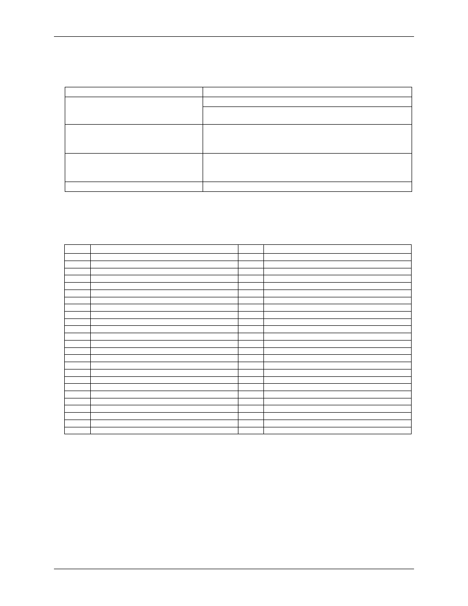
Table 5. Main connector specifications
Connector type
50-pin header
Compatible cables
C50FF-x: 50-pin IDC female to female cable. x = length in feet.
C50-37F-x: 50-pin IDC to 37-pin female D connector (adaptor cable for
connecting to a PCI-PDISO8 compatible interface). x = length in feet.
Compatible accessory products
(using the C50FF-x cable)
CIO-MINI50
CIO-TERM100
SCB-50
Compatible accessory products
(using the C50-37F-x cable)
CIO-MINI37
CIO-TERMINAL
SCB-37
Max current
3 A
Note that the PCI-PDISO16 board has two 50-pin connectors, identified on the board as P2 and P3. P2 is
located adjacent to the main I/O connector bracket at the left side of the board. P3 is located towards the
middle-right side of the board.
Table 6. P2 connector pin out
Pin
Signal Name
Pin
Signal Name
50
NC
49
NC
48
NC
47
NC
46
NC
45
NC
44
NC
43
NC
42
NC
41
NC
40
RELAY 6 (NC)
39
RELAY 5 (NC)
38
RELAY 7 (NC)
37
RELAY 0 (NO)
36
RELAY 0 (C)
35
RELAY 0 (NC)
34
RELAY 1 (NO)
33
RELAY 1 (C)
32
RELAY 1 (NC)
31
RELAY 2 (NO)
30
RELAY 2 (C)
29
RELAY 2 (NC)
28
RELAY 3 (NO)
27
RELAY 3 (C)
26
RELAY 3 (NC)
25
RELAY 4 (NO)
24
RELAY 4 (C)
23
RELAY 4 (NC)
22
RELAY 5 (NO)
21
RELAY 5 (C)
20
RELAY 6 (NO)
19
RELAY 6 (C)
18
RELAY 7 (NO)
17
RELAY 7 (C)
16
INPUT 0
15
INPUT 0
14
INPUT 1
13
INPUT 1
12
INPUT 2
11
INPUT 2
10
INPUT 3
9
INPUT 3
8
INPUT 4
7
INPUT 4
6
INPUT 5
5
INPUT 5
4
INPUT 6
3
INPUT 6
2
INPUT 7
1
INPUT 7