Connecting the board for i/o operations, Connectors, cables – main i/o connector – Measurement Computing PCI-PDISO16 User Manual
Page 12
PCI-PDISO16 User's Guide
Installing the PCI-PDISO16
12
Connecting the board for I/O operations
Connectors, cables
– main I/O connector
The table below lists the board connectors, applicable cables and compatible accessory boards.
Board connectors, cables, accessory equipment
Connector type
50-pin IDC type
Compatible cables
C50FF-x: 50-pin IDC female to female cable. x = length in feet.
C50-37F-x: 50-pin IDC to 37-pin female D connector (adaptor cable for
connecting to a PCI-PDISO8 compatible interface). x = length in feet.
Compatible accessory products
(using C50FF-x cable)
CIO-MINI50
CIO-TERM100
SCB-50
Compatible accessory products
(using C50-37F-x cable)
CIO-MINI37
CIO-TERMINAL
SCB-37
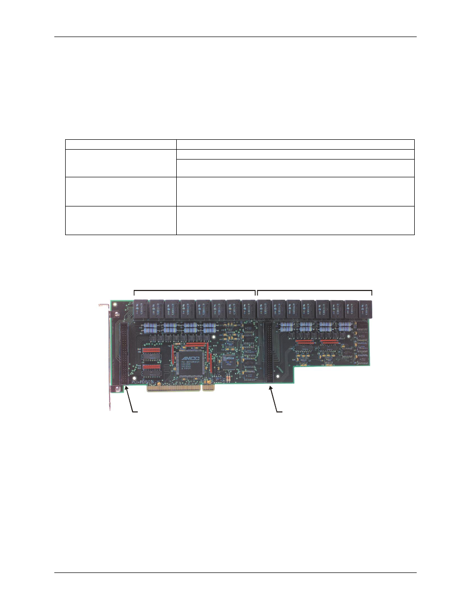
The PCI-PDISO16 board has two 50-pin connectors for signal I/O connections that are labeled on the board as
P2
and
P3
. P2 is located adjacent to the main I/O connector bracket at the left side of the board. P3 is located
towards the middle-right side of the board. Figure 2 shows the location of the board connectors and relays.
Connector P2
Connector P3
P2 Relays 0-7
P3 Relays 0-7
Figure 2. Connector and relay locations