Functional description, Isolated inputs, Extending the input range – Measurement Computing PCI-PDISO16 User Manual
Page 16
16
Chapter 3
Functional Description
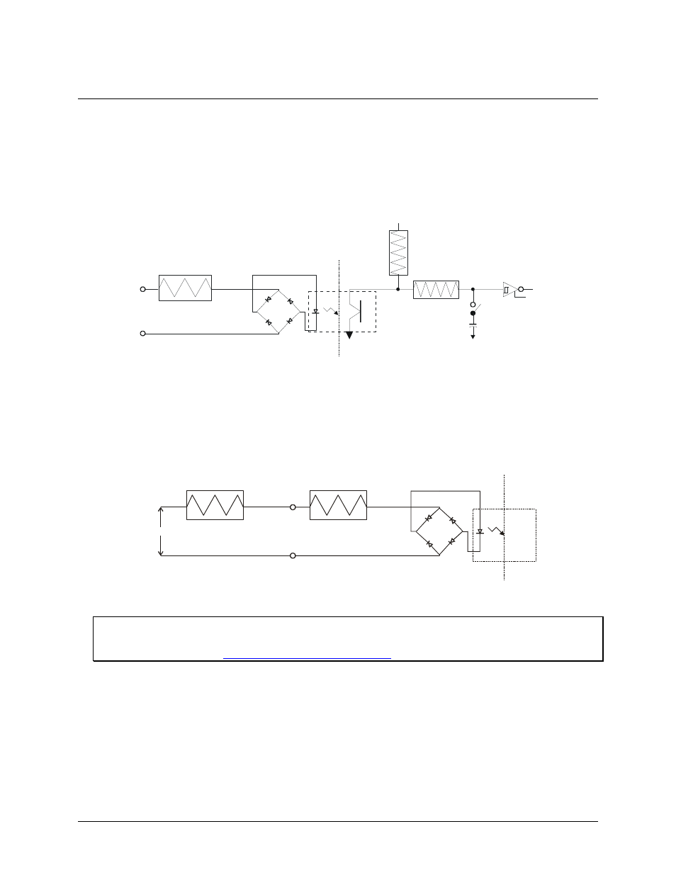
Isolated inputs
The PCI-PDISO16 board has eight isolated input channels. A schematic of a single channel is shown in Figure
6. The signals are routed through a bridge rectifier so that the inputs are not polarity sensitive.
470 Ohm
Isolated Input
Not Polarized
Circuitry Sharing
PC Ground
Filter Switch
0.1uF
47K
+5V
100K
Figure 6. Isolated input channel - simplified schematic
Extending the input range
To extend the input range beyond the 5-28V specified, add an external resistor. Figure 7 shows the resistor and
the equations used to calculate resistor values for a given V
in
.
1.6 K
Isolated Input
Not Polarized
R ext
V
in
R ext = 100 * (Vin - 28)
Pw = R ext / 10 000
Figure 7. Input voltage range extender resistor
Digital I/O Techniques
For more information about digital I/O techniques, refer to the Guide to Signal Connections. This document is
available on our web sit
- ACC-300 (7 pages)
- AI-EXP32 (20 pages)
- AI-EXP48 (19 pages)
- BTH-1208LS (30 pages)
- 6K-ERB08 (32 pages)
- BTH-1208LS Quick Start (4 pages)
- 6K-SSR-RACK08 (33 pages)
- BTH-1208LS-OEM (27 pages)
- CB-COM-Digital (68 pages)
- CB-7018 (68 pages)
- CB-7000 Utilities (44 pages)
- CB-7080D (74 pages)
- CB-COM-7033 (44 pages)
- CB-COM-7017 (72 pages)
- CB-COM-7024 (76 pages)
- CB-NAP-7000P (36 pages)
- CIO-DAC02/16 (16 pages)
- CIO-DAC02 (18 pages)
- CB-NAP-7000D (56 pages)
- CIO-DAC16-I (16 pages)
- CIO-DAC16/16 (20 pages)
- CIO-DAS08 (21 pages)
- CIO-DAC16 (20 pages)
- CIO-DAS08/JR (16 pages)
- CIO-DAS08/JR/16 (14 pages)
- CIO-DAS08/JR-AO (16 pages)
- CIO-DAS08-AOM (32 pages)
- CIO-DAS08-PGM (28 pages)
- CIO-DAS16/330 (34 pages)
- CIO-DAS48-I (17 pages)
- CIO-DAS16/M1 (38 pages)
- CIO-DAS48-PGA (18 pages)
- CIO-DAS800 (20 pages)
- CIO-DAS802/16 (22 pages)
- CIO-DAS6402/16 (40 pages)
- CIO-DAS-TEMP (20 pages)
- CIO-DDA06/16 (18 pages)
- CIO-DDA06/JR (17 pages)
- CIO-DIO24/CTR3 (21 pages)
- CIO-DIO24H (20 pages)
- CIO-DI192 (24 pages)
- CIO-DDA06 (21 pages)
- CIO-DIO48 (19 pages)
- CIO-DO192H (16 pages)
- CIO-DIO192 (20 pages)