Pci-pdiso8 compatibility – Measurement Computing PCI-PDISO16 User Manual
Page 14
PCI-PDISO16 User's Guide
Installing the PCI-PDISO16
14
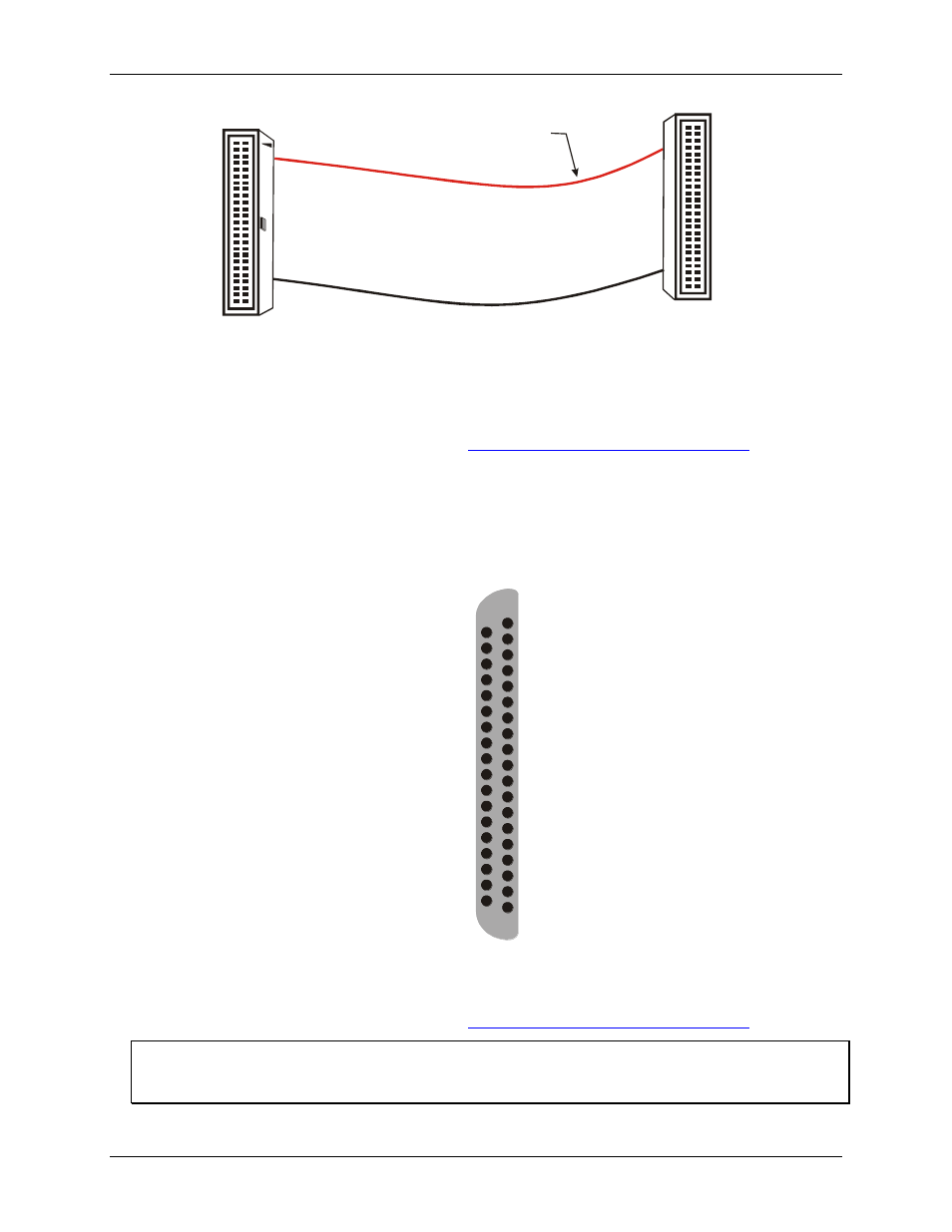
The red stripe
identifies pin # 1
50-pin Female
IDC connector
50-pin Female
IDC Connector
1
2
49
50
1
49
50
2
Figure 3. C50FF-x cable
Details on this cable are available on our web sit
PCI-PDISO8 compatibility
For connections to a PCI-PDISO8 compatible interface, use a C50-37F-x adaptor cable. This cable converts the
PCI-PDISO16 board’s connector to a PDIS08-compatible D connector. Two adaptor cables are required if more
than eight relays are used. Pin assignments for the C50-37F-x cable are shown in Figure 4.
RELAY 0 (C)
37
RELAY 1 (NO) 36
RELAY 1 (NC) 35
RELAY 2 (C)
34
RELAY 3 (NO) 33
RELAY 3 (NC) 32
RELAY 4 (C)
31
RELAY 5 (NO) 30
RELAY 6 (NO) 29
RELAY 7 (NO) 28
INPUT 0
27
INPUT 1
26
INPUT 2
25
INPUT 3
24
INPUT 4
23
INPUT 5
22
INPUT 6
21
INPUT 7
20
19 RELAY 0 (NO)
18 RELAY 0 (NC)
17 RELAY 1 (C)
16 RELAY 2 (NO)
15 RELAY 2 (NC)
14 RELAY 3 (C)
13 RELAY 4 (NO)
12 RELAY 4 (NC)
11 RELAY 5 (C)
10 RELAY 6 (C)
9 RELAY 7 (C)
8 INPUT 0
7 INPUT 1
6 INPUT 2
5 INPUT 3
4 INPUT 4
3 INPUT 5
2 INPUT 6
1 INPUT 7
(NO) = Normally Open, (C) = Common, (NC) = Normally Closed
Figure 4. C50-37F-x adaptor cable pin out
Details on this cable are available on our web sit
Note
The RELAY 5, 6 and 7 NC terminals on the PCI-PDISO16 board’s 50-pin I/O connector (pin 38, 39 and 40) are
not accessible when using the C50-37F-x adaptor cable.