Measurement Computing PCI-DAS1200 User Manual
Page 14
PCI-DAS1200 User's Guide
Installing the PCI-DAS1200
13
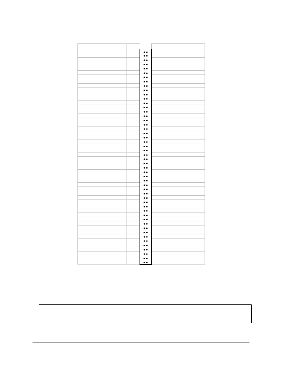
16-channel single-ended mode pin out
Signal Name Pin
Pin
Signal Name
PC GND
100
50
PC GND
N/C
99
49
N/C
N/C
98
48
PC +5V
N/C
97
47
N/C
N/C
96
46
N/C
A/D Internal Pacer Output
95
45
A/D External Trigger
N/C
94
44
N/C
N/C
93
43
N/C
PC -12V
92
42
A/D External Pacer
PC GND
91
41
OUT 4
PC +12V
90
40
GATE 4
PC GND
89
39
CLK 4
N/C
88
38
D/A OUT 1
OUT 5
87
37
D/A GND 1
GATE 5
86
36
D/A OUT 0
CLK 5
85
35
D/A GND 0
N/C
84
34
N/C
N/C
83
33
N/C
OUT 6
82
32
N/C
GATE 6
81
31
N/C
CLK 6
80
30
N/C
N/C
79
29
N/C
N/C
78
28
N/C
10 MHz OUT
77
27
N/C
N/C
76
26
N/C
N/C
75
25
N/C
FIRSTPORTC Bit 7
74
24
N/C
FIRSTPORTC Bit 6
73
23
N/C
FIRSTPORTC Bit 5
72
22
N/C
FIRSTPORTC Bit 4
71
21
N/C
FIRSTPORTC Bit 3
70
20
N/C
FIRSTPORTC Bit 2
69
19
N/C
FIRSTPORTC Bit 1
68
18
Analog GND
FIRSTPORTC Bit 0
67
17
CH15 IN
FIRSTPORTB Bit 7
66
16
CH7 IN
FIRSTPORTB Bit 6
65
15
CH14 IN
FIRSTPORTB Bit 5
64
14
CH6 IN
FIRSTPORTB Bit 4
63
13
CH13 IN
FIRSTPORTB Bit 3
62
12
CH5 IN
FIRSTPORTB Bit 2
61
11
CH12 IN
FIRSTPORTB Bit 1
60
10
CH4 IN
FIRSTPORTB Bit 0
59
9
CH11 IN
FIRSTPORTA Bit 7
58
8
CH3 IN
FIRSTPORTA Bit 6
57
7
CH10 IN
FIRSTPORTA Bit 5
56
6
CH2 IN
FIRSTPORTA Bit 4
55
5
CH9 IN
FIRSTPORTA Bit 3
54
4
CH1 IN
FIRSTPORTA Bit 2
53
3
CH8 IN
FIRSTPORTA Bit 1
52
2
CH0 IN
FIRSTPORTA Bit 0
51
1
Analog GND
PCI slot
↓
All I/O signals are brought through a 100-pin high-density connector. You can use a C100FF-x to connect field
signals to the board (Figure 2). This cable has a pair of 50-pin ribbon cables joined at one end to a 100-pin
connector. The first 50-pin cable (pins 1-50) carries the analog signals. The second 50-pin cable (pins 51-100)
carries the digital signals. The 100-pin connector mates with the PCI-DAS1200 connector. The two 50-pin
ribbon cables are terminated with standard 50-pin header connectors.
Information on signal connections
General information regarding signal connection and configuration is available in the Guide to Signal
Connections. This document is available on our web sit