Connecting the board for i/o operations – Measurement Computing PCI-DAS1200 User Manual
Page 12
PCI-DAS1200 User's Guide
Installing the PCI-DAS1200
11
Differential input mode
When all channels are configured for differential input mode, eight analog input channels are available. In this
mode, the input signal is measured with respect to the low input. The input signal is delivered through three
wires:
The wire carrying the signal to be measured connects to CH# IN HI.
The wire carrying the reference signal connects to CH# IN LO.
The third wire is connected to LLGND.
Differential input mode is the preferred configuration for applications in noisy environments, or when the signal
source is referenced to a potential other than PC ground.
Single-ended input mode
When all channels are configured for single-ended input mode, 16 analog input channels are available. In this
mode, the input signal is referenced to the board’s signal ground (LLGND). The input signal is delivered
through two wires:
The wire carrying the signal to be measured connects to CH# IN HI.
The second wire is connected to LLGND.
Connecting the board for I/O operations
Connectors, cables – main I/O connector
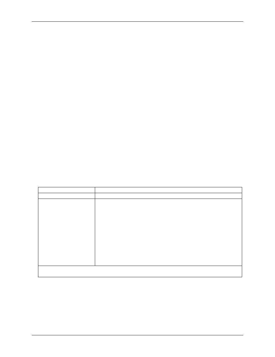
The table below lists the board connectors, applicable cables and compatible accessory boards.
Board connectors, cables, accessory equipment
Connector type
100-pin high density
Compatible cable
C100FF-x, unshielded ribbon cable. x = length in feet
Compatible accessory products
(with the C100FF-x cable)
ISO-Rack16/P
ISO-DA02/P
CIO-ERB08*
CIO-ERB24*
CIO-SERB24*
SSR-RACK08*
SSR-RACK24*
BNC-16SE
BNC-16DI
CIO-MINI50 (2 required)
CIO-TERM100 (1 required)
SCB-50 (1 required)
* These devices require the DADP-5037 PCI-DAS to 37-pin SSR and ERB adapter board.
The CIO-ERB08 device also requires the TN-MC78M05CT voltage regulator.