Cabling, Field wiring and signal termination accessories, Field wiring, signal – Measurement Computing CIO-PDISO8 User Manual
Page 13: Termination and conditioning, Ge 12, 12 cabling
CIO-PDISO8 User's Guide
Installing the CIO-PDISO8
12
Cabling
20
1
37
19
20
1
37
19
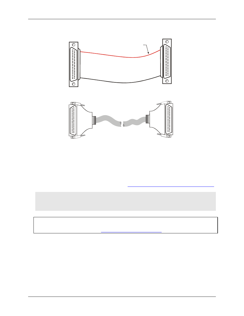
The red stripe
identifies pin # 1
Figure 6. C37FF-x cable
37
19
20
1
20
1
37
19
37
20
1
20
1
37
19
Figure 7. C37FFS-x cable
Field wiring and signal termination accessories
You can connect the CIO-PDISO8 to the following accessory boards using the C37FF-x cable.
CIO-MINI37 – 37-pin screw terminal board.
SCB-37 – 37-conductor, shielded signal connection/screw terminal box.
Details on these products are available on our web sit
Caution! Do not use exposed-screw terminal boards if your field voltage is more than 24 volts. Using a
screw terminal board with high voltage inputs or outputs exposes you and others to those high
voltage signals. Construct a safe cable to carry your signals directly from your equipment to the
CIO-PDISO8 connector.
For additional information about digital interfacing
Detailed information regarding digital interfacing is contained in MCC's Guide to Signal Connections. This
document is available on our web sit