Connecting the board for i/o operations, Connectors, cables – main i/o connector, Pin out – main i/o connector – Measurement Computing CIO-PDISO8 User Manual
Page 12
CIO-PDISO8 User's Guide
Installing the CIO-PDISO8
11
Connecting the board for I/O operations
Connectors, cables
– main I/O connector
The table below lists the board connectors, applicable cables and compatible accessory boards.
Board connectors, cables, accessory equipment
I/O connector type
37-pin D connector
Compatible cables
C37FF-x, where x = length in feet
C37FFS-x, where x =5 or 10 feet
Compatible accessory products
(with the C37FFS-x and C37FF-x cables)
CIO-MINI37
SCB-37
Information on signal connections
General information regarding signal connection and configuration is available in the Guide to Signal
Connections. This document is available on our web sit
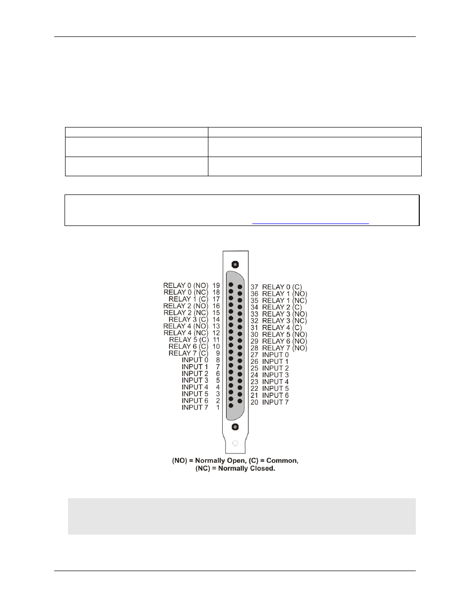
Pin out
– main I/O connector
Figure 5. Main I/O connector pin out
Caution! High voltages are present on the CIO-PDISO8 when you have connected high voltage inputs or
outputs to the CIO-PDISO8 connector. Use extreme caution! Never handle the CIO-PDISO8 when
signals are connected to the board through the connector.
Never remove the protective plates from the CIO-PDISO8.