Functional details, Cio-exp32 inputs, Connecting to a signal source – Measurement Computing CIO-EXP32 User Manual
Page 18: Chapter 3
Chapter 3
Functional Details
CIO-EXP32 inputs
The CIO-EXP32 inputs are screw terminals which will accept 12-22 AWG wire. Each channel has a screw
terminal for signal high, signal low and ground.
The inputs are differential, which require three connections from the signal source to the CIO-EXP32 — Signal
High, Signal Low, and Signal Ground. A typical connection is shown in
Figure 10. Differential channel connections
Signal High
Signal Low
Low Level Ground
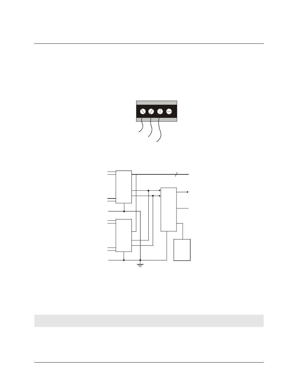
Figure 11. Analog inputs block diagram
shows a block diagram of the board’s 16 analog inputs. One input is selected by the four MUX
address lines that are controlled by the A/D board.
MUX
HI-507
MUX
HI-507
CH15 HIGH
CH15 LOW
CH8 HIGH
CH8 LOW
CH7 HIGH
CH7 LOW
CH0 HIGH
CH0 LOW
GND
GND
Gain
Switch
Gain
Switch
4
EXP out to the
DAS board
Ground
AMP
INA1 10
MUX ADDR
Connecting to a signal source
You can connect analog inputs to the CIO-EXP32 in either a floating differential or differential configuration.
Before connecting to a signal source, measure the voltage between the signal ground at the signal source and
ground at the PC. Do not connect to a signal source if the voltage difference exceeds 10 V, as you will not be
able to obtain a reading.
Caution!
DO NOT connect to the signal if the voltage exceeds 30 V — voltages over 30 V will damage the
board and possibly the computer.
18