Configuring the cio-exp32 – Measurement Computing CIO-EXP32 User Manual
Page 12
CIO-EXP32 User's Guide
Installing the CIO-EXP32
Configuring the CIO-EXP32
Before using the CIO-EXP32, there are switches and jumpers to set, and one or more cables to install. Please
turn the PC power OFF before proceeding. The CIO-EXP32 is shipped with the factory-default settings listed in
the following table.
Factory-configured default settings
Jumper/switch
Description
Default setting
Power source select switch
S3
+5V power switch that sets the power
source to internal or external
INT (internal +5V PC power)
A/D BOARD TYPE jumper
Selects DAS08 or DAS16 compatibility
DAS08
EXP OUTPUT TO DAS
jumper
Selects the A/D board channel to connect
the multiplexed analog output to.
CH 0 to 15: 0
CH 16 to 31: 1
(EXP multiplexed output connects to
channel 0 and 1 on the A/D board)
CJC OUTPUT TO DAS
jumper
Selects the A/D board channel to connect
the CJC output to.
7
(CJC circuit connects to channel 7 on the
A/D board)
GAIN switches
S1 and S2
Four DIP switches per each bank of 16
inputs that set the gain of the differential
amplifier.
Gain = 1 (all gain switches OFF)
V, C and G solder bridge
switches (one for each input
channel)
Three 'connect pads' per channel on the etch
side (under side) of the CIO-EXP32 board.
Bridge each pad to configures its associated
input channel as follows:
Bridge the
V pads to enable open
thermocouple detection for the associated
input channel.
Bridge the
C pads to connect a 1 µF
capacitor across the signal high and low
inputs, forming a low-pass filter having a
7 Hz cutoff.
Bridge the
G pads to enable a reference
to ground for the associated input
channel.
Open pads (all are not bridged)
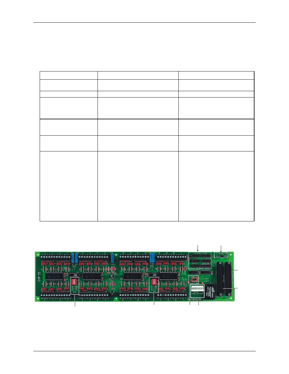
Figure 3. Switch, jumper, and connector locations
shows the location of the board jumpers, switches, and connectors. The solder bridges are on the under
side of the board, and are not shown in the figure.
A/D Board Type
jumper
External power
connector
P29
Gain
switches
S1
EXP and CJC Output to
DAS channel jumpers
Power
source switch
S3
P2
connector
(DAS)
P1
connector
(Next EXP)
Gain
switch
S2
Before using the CIO-EXP32, verify that the board is configured with the settings that you want. Review the
following information to change the default configuration of a jumper, switch, or solder gap.
12