0 interfacing, 1 connector diagrams – Measurement Computing CIO-DO24DD User Manual
Page 9
4.0 INTERFACING
4.1 CONNECTOR DIAGRAMS
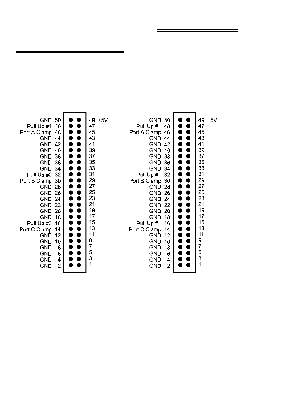
The output connector(s) is a 50-pin header type connector accessible from the rear of
the PC through the expansion back plate (Figure 4-1). The output signals are direct
connections to the Darlington output transistor.
Figure 4-1. Connector Pin Outs
The connectors accepts female 50-pin header type connectors, such as th ose on the
C50FF-2, a 2-foot cable with female connectors.
If frequent changes to signal co nnections or signal co nditioning is required, please
refer to the information on the CIO-TERM100, CIO-SPADE50 and CIO-MINI50
screw terminal boards.
5
1A0
1A1
1A2
1A3
1A4
1A5
1A6
1A7
1B0
1B1
1B2
1B3
1B4
1B5
1B6
1B7
1C0
1C1
1C2
1C3
1C4
1C5
1C6
1C7
P1
CIO-DO24DD PIN OUT or
CIO-DO48DD, P1 CONNECTOR
2A0
2A1
2A2
2A3
2A4
2A5
2A6
2A7
2B0
2B1
2B2
2B3
2B4
2B5
2B6
2B7
2C0
2C1
2C2
2C3
2C4
2C5
2C6
2C7
P2
CIO-DO48DD, P2 CONNECTOR
4
5
6