Measurement Computing CIO-DO24DD User Manual
Page 12
2. The current specification applies on ly when the transistor is on. The
transistor can pass up to 500 mA.
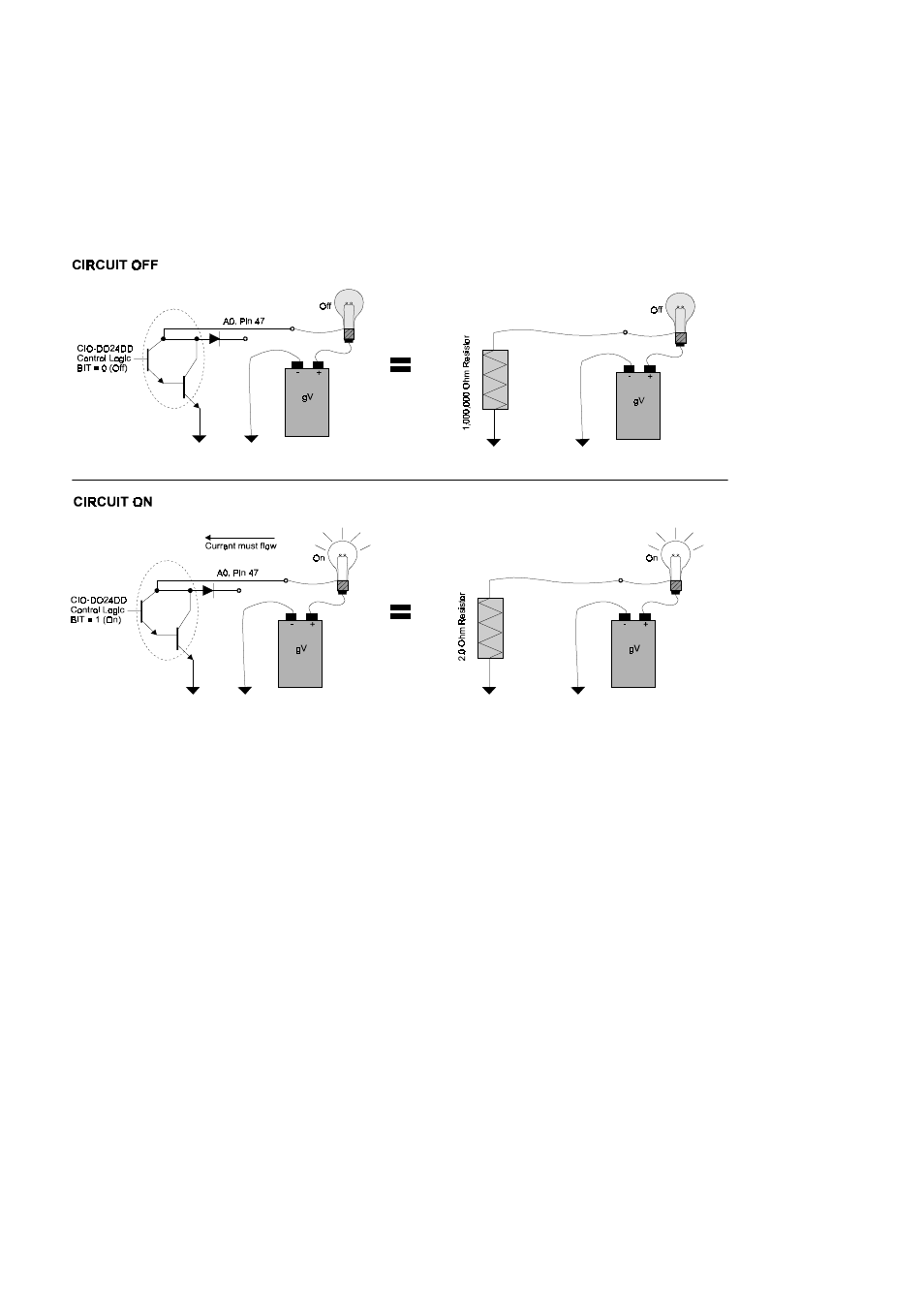
Figure 4-3 is an example of a simple circuit. It shows a lamp with a 9 volt battery.
The positive battery terminal is connected to a co ntact of the lamp. The other lamp
connection is tied to the Darlington output. The negative side of the battery is
connected to GND (pin 44). When you write a 1 to the A0 bit, the Darlington turns on
completing the circuit and the lamp lights.
Figure 4-3. Darlington Explained
Notice in Figure 4-3 above, that an equivalent, simplified circuit based on a resistor is
shown to the right o f the Darlington circuit. The Darlington transistors act like a
switch which alternates between two resistors, one of great resistance and one of
minimal resistance. Notice that when the Darlington is OFF, th ere is some leakage
current flowing. Notice also that when the transistors are ON, there is a small voltage
drop across the Darlington. Both these aspects of the switch should be considered in
the design of your overall circuit.
The current can only flow from the pins labeled A#, B#, and C# to ground, and the PC
must share a common ground with your circuit.
For specifications of the leakage current and ON voltage of the Darlington, please see
the specifications in the back of this manual.
8