Configuring the cio-das08 – Measurement Computing CIO-DAS08 User Manual
Page 9
CIO-DAS08 User's Guide
Installing the CIO-DAS08
Configuring the CIO-DAS08
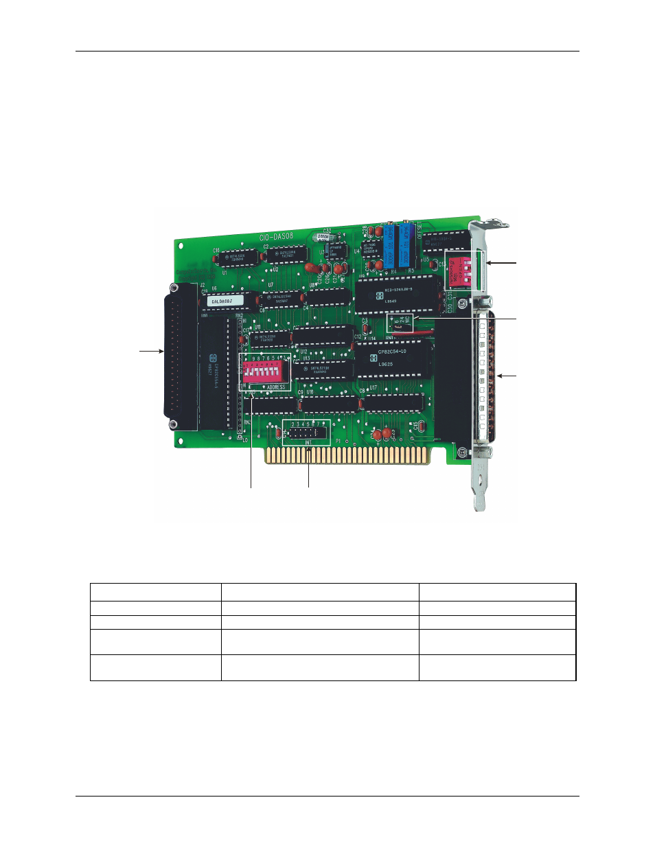
The CIO-DAS08 has two sets of switches and two jumpers that should be set before installing the board in the
PC. Mounted on the board is a bank of DIP switches for setting the base address, a jumper for setting the
interrupt level and a jumper for setting the pacer source to either the internal PC Clock source or an external
clock. A bank of four switches on the connector bracket is used for setting the analog input range.
The InstaCal calibration and test program included with the CIO-DAS08 will show you how to configure the
board. Run InstaCal before you open your computer and install the board.
The location of each switch and jumper on the CIO-DAS08 is shown in
.
Figure 1
Figure 1. Switch and jumper locations
Base Address
switches
Interrupt Level
jumper
Digital
connector
J2
Analog
connector
Analog
Input
Range
switches
Analog
connector
J1
Clock
Source
jumper
The CIO-DAS08 is shipped with the factory-default settings listed in the table below.
Factory-configured default settings
Switch/jumper Description
Default
setting
Base address DIP switches
Sets the base address
300h (768 decimal)
Interrupt level jumper
Sets the interrupt level
"X" position (no interrupt level set)
Clock source jumper
Sets the pacer source as the internal PC clock or
an external clock
"24/NC" position (external source)
Analog input range and gain
Sets the analog input range and gain
±5V
Review the following information to change the default configuration of a jumper or switch.
9