Specifications, Analog input, Digital input / output – Measurement Computing CIO-DAS08 User Manual
Page 17: Chapter 4
Chapter 4
Specifications
Typical for 25 °C unless otherwise specified.
Specifications in italic text are guaranteed by design.
Analog input
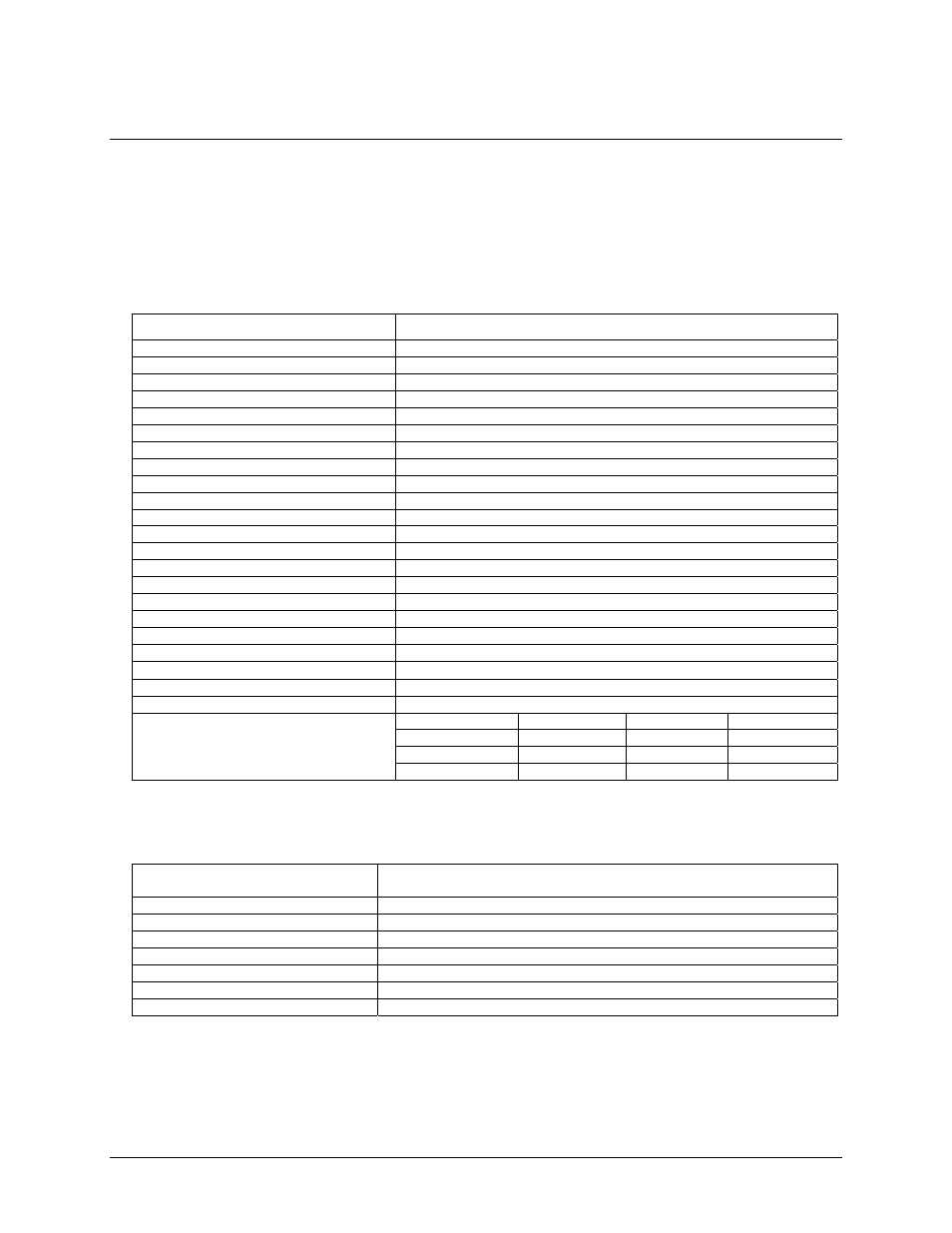
Table 1. Analog input specifications
Parameter Specification
A/D converter type
AD574
Resolution 12-bits
Number of channels
8 single-ended
Input ranges
±10 V, ±5 V, 0 to +10 V, switch selectable
Polarity
Unipolar/Bipolar, switch selectable
A/D pacing
Software polled (typically through ISR paced by on-board counter)
A/D trigger sources
External polled digital input trigger (Digital In 1)
Data transfer
Software polled (typically through ISR paced by on-board counter)
DMA None
A/D conversion time
25 µs
Throughput
20 kHz, PC dependent
Accuracy
±0.01% of reading ±1 LSB
Differential linearity error
±1 LSB
Integral linearity error
±0.5 LSB
No missing codes guaranteed
12-bits
Gain drift (A/D specs)
±25 ppm/°C
Zero drift (A/D specs)
±10 µV/°C
Common Mode Range
±10 V
CMRR 72
dB
Input leakage current (@ 25
°C)
100 nA
Input impedance
10 Meg Ohms min
Absolute maximum input voltage
±35 V
Avg % ± 2 bins
Avg % ± 1 bin
Avg # bins
Bipolar (10 V)
100%
100%
3 bins
Bipolar (5 V)
100%
100%
3 bins
Noise Distribution (Rate = 1 to 20 kHz)
Unipolar (10 V)
100%
100%
3 bins
Digital Input / Output
Table 2. Digital input/output specifications (main connector – J1)
Digital type (main connector J1)
Output: 74LS273
Input: 74LS244
Configuration
4 fixed output bits, 3 fixed input bits
Number of channels
4 out, 3 in
Output high
2.7 volts min @ -0.4 mA
Output low
0.4 volts max @ 8 mA
Input high
2.0 volts min, 7 volts absolute max
Input low
0.8 volts max, -0.5 volts absolute min
Output power-up / reset state
17