Pin out – digital connector (j2), Cabling – Measurement Computing CIO-DAS08 User Manual
Page 14
CIO-DAS08 User's Guide
Installing the CIO-DAS08
Pin out – Digital connector (J2)
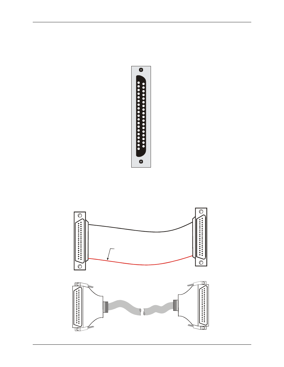
The digital connector (J2) is a 37-pin, type D connector that is mounted on the CIO-DAS08 board (see
). This connector is identical to the CIO-DIO24 connector, except that the Interrupt Input and Interrupt Enable
pins are not provided. These are no-connect pins (NC) on the CIO-DAS08. The CIO-DAS08 has an interrupt
input pin at pin 24 on the analog connector J1.
Figure 7. 37-pin digital connector
GND 19
+5V 18
GND 17
+12V 16
GND 15
-12V 14
GND 13
-5V 12
GND 11
10
9
8
7
6
5
4
FIRSTPORTB Bit 7 3
NC 2
NC 1
FIRSTPORTB Bit 0
FIRSTPORTB Bit 1
FIRSTPORTB Bit 2
FIRSTPORTB Bit 3
FIRSTPORTB Bit 4
FIRSTPORTB Bit 5
FIRSTPORTB Bit 6
37
36
35
34
33
32
31
30
29
28
27
26
25
24
23
22
21 GND
20 +5V
FIRSTPORTA Bit 0
FIRSTPORTA Bit 1
FIRSTPORTA Bit 2
FIRSTPORTA Bit 3
FIRSTPORTA Bit 4
FIRSTPORTA Bit 5
FIRSTPORTA Bit 6
FIRSTPORTA Bit 7
FIRSTPORTC Bit 0
FIRSTPORTC Bit 1
FIRSTPORTC Bit 2
FIRSTPORTC Bit 3
FIRSTPORTC Bit 4
FIRSTPORTC Bit 5
FIRSTPORTC Bit 6
FIRSTPORTC Bit 7
Use a BP-37 backplate and cable assembly to bring signals from the digital connector to the backplate. BP-37
terminates with a 37-pin male backplate connector. You can run a standard C37FF-2 cable alongside the analog
connector (J1) through the gap in the expansion slot backplate.
Cabling
19
37
1
20
19
37
1
20
The red stripe
identifies pin # 1
Figure 8. C37FF-x cable
19
1
37
20
37
20
19
1
Figure 9. C37FFS-x cable
14