Introducing the cio-dac02, Overview: cio-dac02 features, Cio-dac02 block diagram – Measurement Computing CIO-DAC02 User Manual
Page 7: Software features, Chapter 1, The cio-dac02 board
7
Chapter 1
Introducing the CIO-DAC02
Overview: CIO-DAC02 features
The CIO-DAC02 provides two channels of 12-bit analog voltage or current output. Each analog output is
controlled by a 12-bit D/A converter. A 12-bit converter provides 1/4096 parts resolution. On a scale of 0-5
volts, the output can be controlled to within 1.22 mV.
The output voltage reference for each D/A is jumper-selectable for Bipolar or Unipolar. Bipolar ranges are ±10
V and ±5 V. Unipolar ranges are 0 to 10 V, 0 to 5 V, and 4 to 20 mA. You can also provide an external voltage
reference via connections to the board's 25-pin connector.
The board also features a wait state generator that you enable with an on-board jumper.
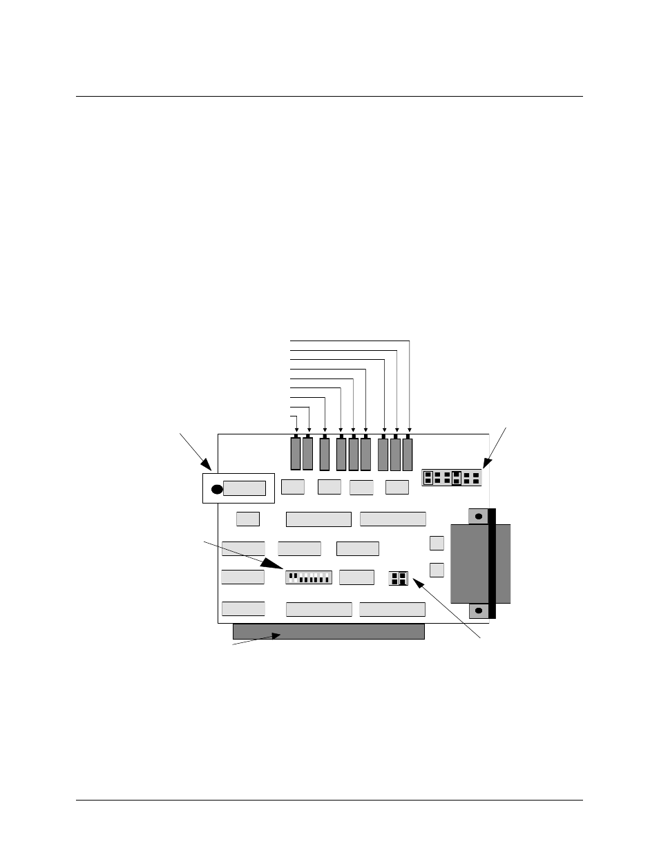
CIO-DAC02 block diagram
D/A1 bipolar gain
D/A1 unipolar offset
D/A1 4-20 gain, unipolar gain & bipolar offset
D/A0 bipolar gain
D/A 0 unipolar offset
D/A0 4-20 gain, unipolar gain & bipolar offset
VREF adjust
4-20 #1 offset
4-20 #0 offset
VREF Jumper Block
Wait State Jumper
PC/XT/AT Bus Connector
i 0
i Out buffer
D /A c o n v e r te r 0
D/A converter 1
U n i 0
B i p 0
U n i 1
B i p 1
D / A 0
D / A 1
-
5
-
1
0
E
X
T
-
5
-
1
0
E
X
T
U P
D N
9 8 7 6 5 4 3 2
i 1
Wait State
6.95 Volt Reference Circuit
THE CIO-DAC02 BOARD
Base Address Switch
Figure 1. CIO-DAC02 functional block diagram
Software features
For information on the features of InstaCal and the other software included with your CIO-DAC02, refer to the
Quick Start Guide that shipped with your device.