Voltage reference jumpers, Installing the cio-dac02 – Measurement Computing CIO-DAC02 User Manual
Page 11
CIO-DAC02 User's Guide
Installing the CIO-DAC02
11
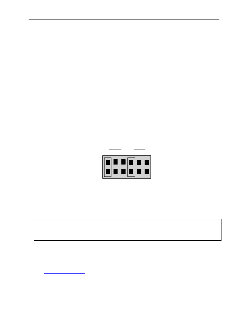
Voltage reference jumpers
The output voltage of the D/A converters is determined by the value of the reference voltage (VREF) and the
digital code written to the DACs (refer to the Analog outputs section on page 13). The VREF signal must be
supplied to each D/A or no voltage output will be present at the D/A's output pin. The VREF is supplied via
jumpers or from an external source.
A jumper block consisting of two rows of six pins is located on the upper right corner of the board. There are
two groups of pins — one for D/A 0 and one for D/A 1. Each group of pins provide a means of supplying either
-5V or -10V to each D/A.
The board is shipped with both the D/A 0 and D/A 1 VREF jumpers in the external (X) position. With jumpers
in the X position, the required D/A reference voltage(s) must be supplied to the 25-pin connector VREF input
pins.
A -5VREF provides a ±5V output on the D/A bipolar output, 0-5V output on the unipolar output and a 4-20
mA output on the current output.
If other ranges are desired, an external voltage between -10 and +10 volts should be supplied.
The on-board voltage reference jumper supplies the same signals available at the 25-pin connector directly to
the D/A VREF input, without the bother of looping the -5VREF or -10VREF outputs back into the D/A VREF
inputs, as is required with the MetraByte DAC-02.
OUTPUT RANGE SELECT JUMPER BLOCK -
The jumpers are in the -5V REF position.
-5 -10 X -5 -10 X
D/A 0
D/A 1
Figure 4. Voltage reference jumpers
Installing the CIO-DAC02
After you configure the board's switches and jumpers, you can install the CIO-DAC02 into your computer. To
install your board, follow the steps below.
Install the MCC DAQ software before you install your board
The driver needed to run your board is installed with the MCC DAQ software. Therefore, you need to install
the MCC DAQ software before you install your board. Refer to the Quick Start Guide for instructions on
installing the software.
1. Turn your computer off, open it up, and insert your board into an available ISA slot.
2. Close your computer and turn it on.
3. To test your installation and configure your board, run the InstaCal utility you installed in the previous
section. Refer to the Quick Start Guide that came with your boar
for information on how to initially set up and load InstaCal.