Connecting the board for i/o operations, Connectors, cables – main i/o connector, Pinout – main i/o connector – Measurement Computing CIO-DAC02 User Manual
Page 12: Field wiring, signal termination, and conditioning, Field, Wiring, signal termination, and conditioning
CIO-DAC02 User's Guide
Installing the CIO-DAC02
12
Connecting the board for I/O operations
Connectors, cables
– main I/O connector
The table below lists the board connector, applicable cables, and compatible accessory products.
Board connector, cables, and accessory equipment
Connector type
25-pin D type connector
Compatible cables
C25FM-x
DMCON-25 (D-connector, D-shell, and termination pins to construct your own
cable)
Compatible accessory products with
the C25FM-x cable
CIO-MINI25
Information on signal connections
General information regarding signal connection and configuration is available in the Guide to Signal
Connections (availa
.
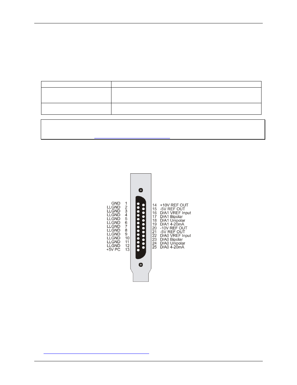
Pinout
– main I/O connector
The CIO-DAC02 I/O connector is a standard 25-pin male D connector that is accessible through the expansion
backplate.
Figure 5. I/O connector pin-out
Field wiring, signal termination, and conditioning
You can use the following cabling, screw termination, and signal conditioning products with the CIO-DAC02.
CIO-MINI25 – 25-pin screw terminal board.
DMCON-25 – Connector kit that includes a 25-pin male D-connector, D-shell, 25 crimp pins, and cable
termination kit to construct your own cable.
Details on these products are available on our web site at