Bulkhead signals, Battery charging, Power and pairing control – Measurement Computing BTH-1208LS-OEM User Manual
Page 16: Led control, Trigger input, Counter input
BTH-1208LS-OEM User's Guide
Functional Details
16
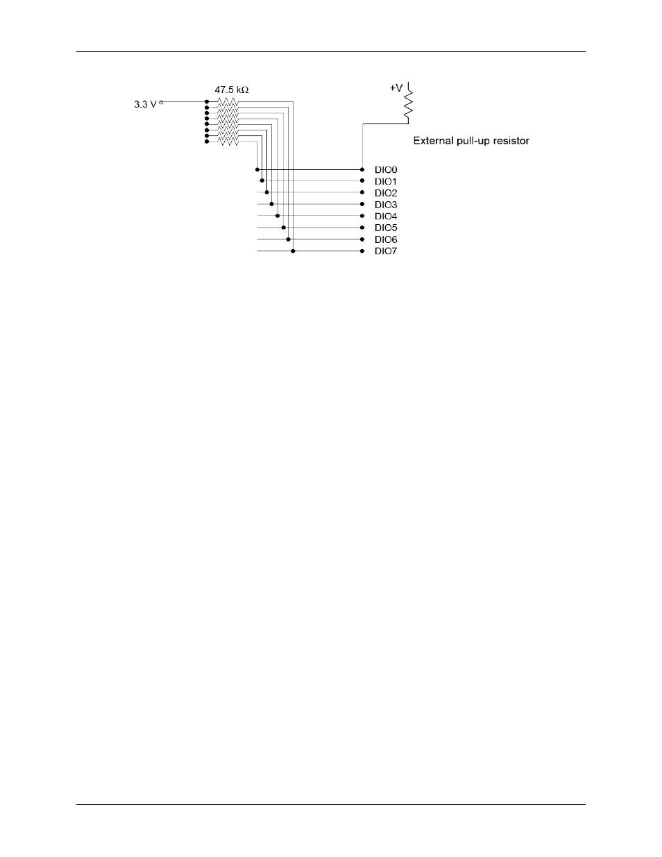
Figure 4. Digital I/O external resistor configuration
Bulkhead signals
The function of the bulkhead pins is explained below.
Battery charging
Use the BATT+, BATT_MID, and BATT– pins to charge two AA or AAA cells used in series, with
BATT_MID connected to the midpoint of the series cells. This enables the charger to detect the voltage of the
cells independently in order to stop fast charging when either cell reaches full capacity.
Also you must use the THERMISTOR+ and THERMISTOR– pins to connect to a 10 k
Ω thermistor in close
proximity to the battery cells to monitor battery temperature.
External power supply (battery charging not required)
Use the BATT+ and BATT– pins to supply power to the board when battery charging is not required. Power
can be supplied from any DC source in the 1.8 V to 5.5 V range.
Power and pairing control
Use the PWR_SW+ and PWR_SW– pins with an external SPST power switch to turn the board on and off.
Use the PAIRING_SW+ and PAIRING_SW– with a momentary switch to perform the same power and pairing
functionality as the onboard button (refer to Power/pairing button on page 12).
LED control
Use the LED1+ and LED1– pins to connect an external power LED. The series resistor is already on the
BTH-1208LS-OEM; only a LED is required.
Use the LED2+ and LED2– pins to connect an external status LED. The series resistor is already on the
BTH-1208LS-OEM; only a LED is required.
Use the Vbus pin to connect to an external charging LED or to power external circuits from a +5 V supply when
a USB host or power supply is present.
Use the CHARGE_LED– pin in combination with the Vbus pin for an external charging LED. The series
resistor is already on the BTH-1208LS-OEM; only a LED is required.
Trigger input
The
TRIG_IN
pin on connector J2 is an external digital trigger input that you can configure for either
rising/falling edge, or high/low level.
Counter input
The
CTR
pin on connector J2 is a 32-bit event counter that can accept frequency inputs up to 1 MHz. The
internal counter increments when the TTL levels transition from low to high.